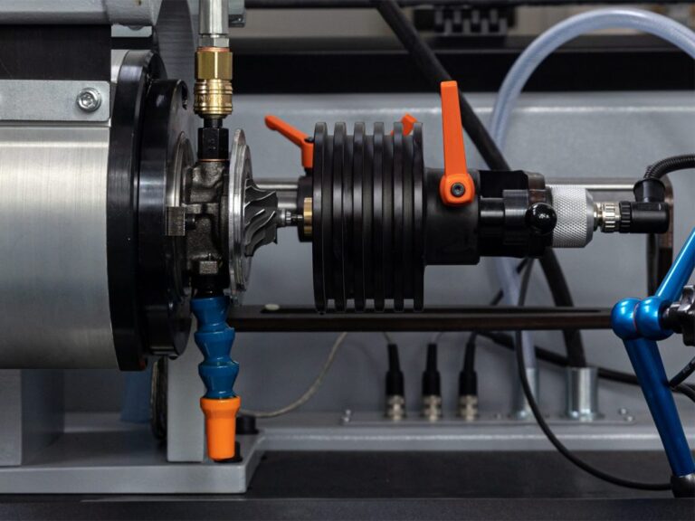
Compensation is a technological process that approximates the indicated imbalance to the actual load on the rotor. Therefore, balancing a disc using a balancing arbor or a fixture on a vertical spindle, without performing compensation, carries the risk of incorrect imbalance identification.
An operator of a balancing machine with a horizontal axis of rotation, commonly called “horizontal,” or with a vertical axis of rotation, called “vertical,” obtaining a balancing result, does not know if the result is correct, even when the indications confirm it. The operator will only find out that the balancing was correct after correcting the mass and accelerating the rotor in its own bearings. Reaccelerating the rotor under the same mounting conditions on the balancing machine as during the first balancing, after correction, will show a residual imbalance consistent with the operator’s expectations. However, the indicated small residual imbalance does not necessarily mean that the actual imbalance of the rotor has been minimized.
If the incorrect imbalance indications resulted from the use of incorrect calibration, then after re-accelerating the rotor, after correction, the imbalance value would remain high. Using the correct calibration but using a poorly prepared balancing arbor on a horizontal balancing machine, or a fixture on a vertical balancing machine, also results in an incorrect result, although the indicated imbalance has a residual value. After accelerating the disc, mounted to its own bearings, unacceptable vibrations will occur. This is because balancing without compensation does not only concern the imbalance of the disc itself. The signals coming from the sensors in the supports contain components from the imbalances of the remaining drive elements and those resulting from the eccentric mounting of the disc (they can be called disturbances). In this disturbance, there are inertial forces from the entire mass of the drive elements or the disc, which are directly proportional to the eccentricity of the individual masses. They have a frequency resulting from the balancing speed. Because their frequency is equal to the balancing frequency, they have not been separated in the balancing machine’s measurement module from the useful signal. This results from the principle operation of the machine. The balancing machine separates (from the signals coming from the sensors in the supports), with the component having a frequency resulting from the rotational speed of the rotor. Everything that is added to this signal is taken into account when determining the imbalance.
Three common sources of identification error
The three most common sources of errors that result in determining the rotor imbalance, which is inconsistent with its actual imbalance, are:
a) the use of an unbalanced spindle with a fixture of a balancing machine with a vertical axis of rotation;
b) eccentric mounting of the balanced part on the balancing arbor or in the fixture, manifested by radial runout;
c) the use of an unbalanced drive with a cardan shaft.
Cases a) and b) occur on balancing machines with a vertical axis of rotation. Cases b) and c) occur on so-called horizontal, universal balancing machines.
Vertical balancing machines and the dimensional chain
A vertical balancing machine is equipped with a vertical spindle with a socket at the top for attaching a fixture. The disc to be balanced is mounted in the fixture.
It can be noticed that the dimensional chain—from the upper bearing in the spindle to the surface used for centering the disc—is long. It consists of kinematic pairs and pairs of centering surfaces. These are kinematic pairs: the spindle head (the lower centering surface in the fixture), the upper centering surface of the fixture (the centering surface of the disc), and a pair of centering surfaces (the lower and upper centering surfaces of the fixture).
On each of these surfaces a centering error occurs, manifested by radial runout. The individual runouts add up geometrically. Thus, a so-called measurement uncertainty area of imbalance is created. It is constant for individual mechanical elements of the drive and variable for each of their assemblies. Out of caution, this area is assumed to not meet the condition of correct centering.
It is possible to eliminate the influence of the eccentricity of the mounting and the imbalance of the fixture on the balancing result by means of compensation. This possibility is of fundamental importance for the quality of balancing in vertical balancing machines. It results from the construction of these machines, where the balanced disc is mounted in a fixture, which is mounted on the other side to the spindle.
The centering cylindrical surface made at the end of the spindle usually exhibits radial runout due to its large distance from the upper bearing in the spindle. Such mounting of the balanced disc to the fixture reveals even trace manufacturing and assembly errors.
Eliminating radial runout: mechanical and electronic
The influence of the total radial runout occurring on the centering surface of the fixture in vertical balancing machines is eliminated by:
a) mechanical means
b) electronic means Similarly, the influence of an unbalanced or misaligned drive using a cardan shaft can be eliminated in horizontal balancing machines.
Mechanical compensation
Mechanical compensation consists of:
a) calculating the mass of the compensating weight based on two measurements of the system’s imbalance: “fixture + rotor” in different angular positions. Such a combination of vectors allows for the selection of the imbalance vector that does not belong to the balanced disc.
b) physically attaching the compensating weight to the fixture with the calculated mass.
After performing this operation, all rotating elements are only loaded by the imbalance of the disc. The compensating weight is mounted on the side of the drive that is permanently connected to the angular scale “seen” by the measurement and calculation system. Often, fixtures have places designated for attaching screws or plastic masses for loading.
Electronic compensation
Electronic compensation differs from mechanical compensation in that instead of a compensating weight, a sinusoidal signal is determined with an amplitude and phase corresponding to the signal. This results from the action of the inertial force from the movement of such a weight. The signal is then summed with the signal coming from the sensor.
Unfortunately, it is not possible to eliminate the angular mounting error, which manifests itself as an axial runout on the disc radius. It can be assumed that with the same value of radial and axial runout, measured for example with a dial gauge, the influence of radial runout on vibrations is greater than that of axial runout.
Due to the lack of repeatability of mounting, it is reasonable to adopt the principle that after each change of the fixture, the compensation procedure should be performed. Balancing machines are factory- equipped with such a procedure.
Compensation is single plane, which means that it does not compensate for moments of force.
Repeatability of mounting
The issue of compensation is related to the so-called repeatability of mounting. The better the repeatability of mounting, the more effective the compensation. This connection results from the need to use at least two, angularly different, mountings of the rotor in order to obtain data for performing compensation.
Repeatability of mounting is distinguished by:
a) occurring in the absence of relative rotation between the balanced part and the elements used to mount it;
b) occurring with relative rotation between the part and the mounting elements.
In the absence of relative rotation between the disc and the mounting elements, when two measurement results obtained with two of its positions at the same angle (the part is mounted, removed and remounted in the same way), are equal (both in terms of value and angle), it is considered that the mounting repeatability is “complete.” This can occur when the disc is mounted without clearance.
If the relative angular position of the disc and shaft is changed, different results will be obtained. In the absence of clearances, the differences in data will result only from the curvature of the shaft occurring at a different angle. Additionally, if there is a clearance in the connection, the influence of the clearance randomly taken up will be added to the influence of the curvature on the result. This means that the measurement result will include radial runout, subject to the sinusoidal change rule, together with the relative rotation (from curvature), and the influence of the randomly taken up clearance in the disc mounting, not subject to any rule.
If the runout at any point on the shaft were measured, the value of the runout changes with rotation, reaching a maximum and a minimum once per revolution. The runout takes on values according to the function along with rotation. This rule is used in compensation.
Data from measurements taken in the presence of clearances, entered into the balancing machine’s calculation system, will identify the shape error of the balancing arbor or the runout of the fixture on the spindle with an accuracy limited by the clearance.
In practice, it is observed that at the beginning of balancing, compensation is effective and allows for obtaining smaller and smaller residual imbalances. For large imbalance values, small mounting errors resulting from clearances do not significantly affect the result. If in the next step of balancing the same disc using compensation, the imbalance does not decrease, it means that the errors resulting from insufficient mounting repeatability cause the occurrence of additional imbalance, which is comparable to the residual imbalance.
Requirements for the balancing arbor
To adequately perform its centering and driving tasks, the shaft should have the following characteristics to ensure sufficient mounting repeatability:
a) the balancing arbor should be machined from a single setup, surface hardened, and ground on at least three bearing surfaces (the journals and the disc mounting location).
b) the diameter for mounting the disc should be made to a tolerance class that matches the tolerance class of the hole in the disc. According to the principle, “the tighter, the better,” practice shows that the fit should be a sliding, slightly press-fit (e.g., H7/g6; with such a fit, the disc can be mounted on the shaft manually).
c) the radial runout between the journals and the disc mounting location should be indicated on the shaft together with the location where the maximum dial gauge reading occurs.
d) the nut that angularly secures the disc should have a minimal weight or be centered on an additional, fitted hole, as the threaded part of the nut does not center it.
The advantage of mechanical compensation is the elimination of the error close to its source. In supercritical balancing machines, the spindle together with the fixture after mechanical compensation does not perform transverse vibrations; while after electronic compensation, it does perform vibrations.
The disadvantage of mechanical compensation is the difficulty associated with the physical production and mounting of the compensating weight on the fixture. The advantage of electronic compensation is the simplicity of use. The disadvantage is the lack of elimination of large forces or vibrations on the supports even after balancing the rotor.
Balancing results show a constant value of imbalance, after correctly performed compensation, with mounting angles that change with the rotation of the disc relative to the fixture. This is the measured actual imbalance of the disc. This means that after removing and re-mounting at a different angle, e.g., by 180°, the result in terms of amplitude will not change, and the angle will rotate in the direction of the change in mounting also by 180°. Compensation is possible when there are small deviations from this principle.
From the above analysis it follows that there is no compensation without repeatability of rotor mounting. Compensation ends where the influence of the non-repeatability of the rotor mounting in the fixture starts to dominate. Therefore, a fundamental requirement placed on the fixture is the matching of the mounting diameters on the fixture to the base diameters on the rotor.
Performing electronic compensation step by step
Electronic compensation of additional and harmful imbalance, e.g., for a disc mounted on a balancing arbor, is performed as follows: a) start the compensation process on the machine’s control panel.
b) mount the disc on the balancing arbor and perform a measurement.
c) after removing and rotating relative to any (or forced by the balancing machine) angle, e.g., 180°, remount the rotor and perform a measurement.
d) finish the compensation process by confirming the data.
Reading the compensation vector diagrams
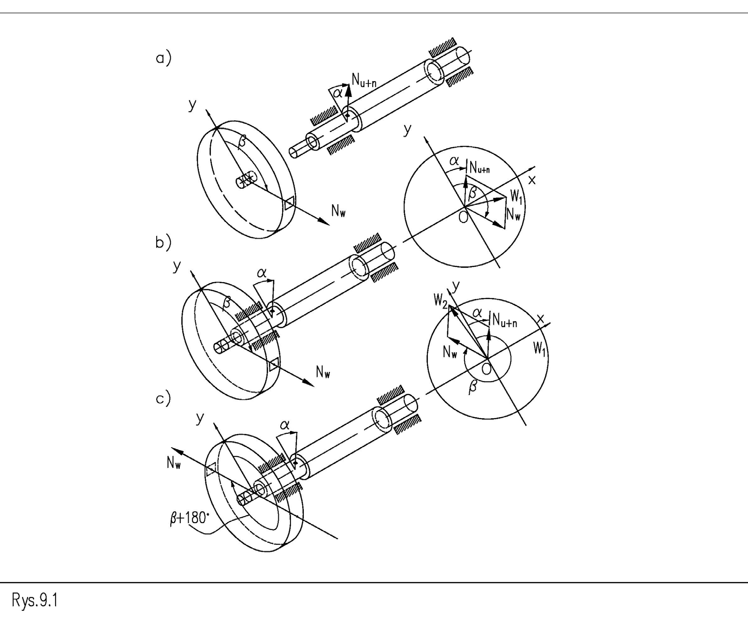
The following figures show the compensation process, where the individual vectors represent:
𝑁𝑁!”# – The imbalance of the fixture + the imbalance caused by the eccentricity of the rotor mounting in the fixture (which needs to be eliminated), 𝑁𝑁$ – The sought-after imbalance of the rotor, 𝑁𝑁$ – The machine indication (or electrical signal) for the assembly of components in position 1, 𝑊𝑊% – The machine indication (or electrical signal) for the assembly of components in position 2, – compensation vector (corresponding electrical signal).
Figure 1. Method for eliminating harmful imbalance originating from the imbalance of the fixture and eccentricity of the rotor mounting in the fixture
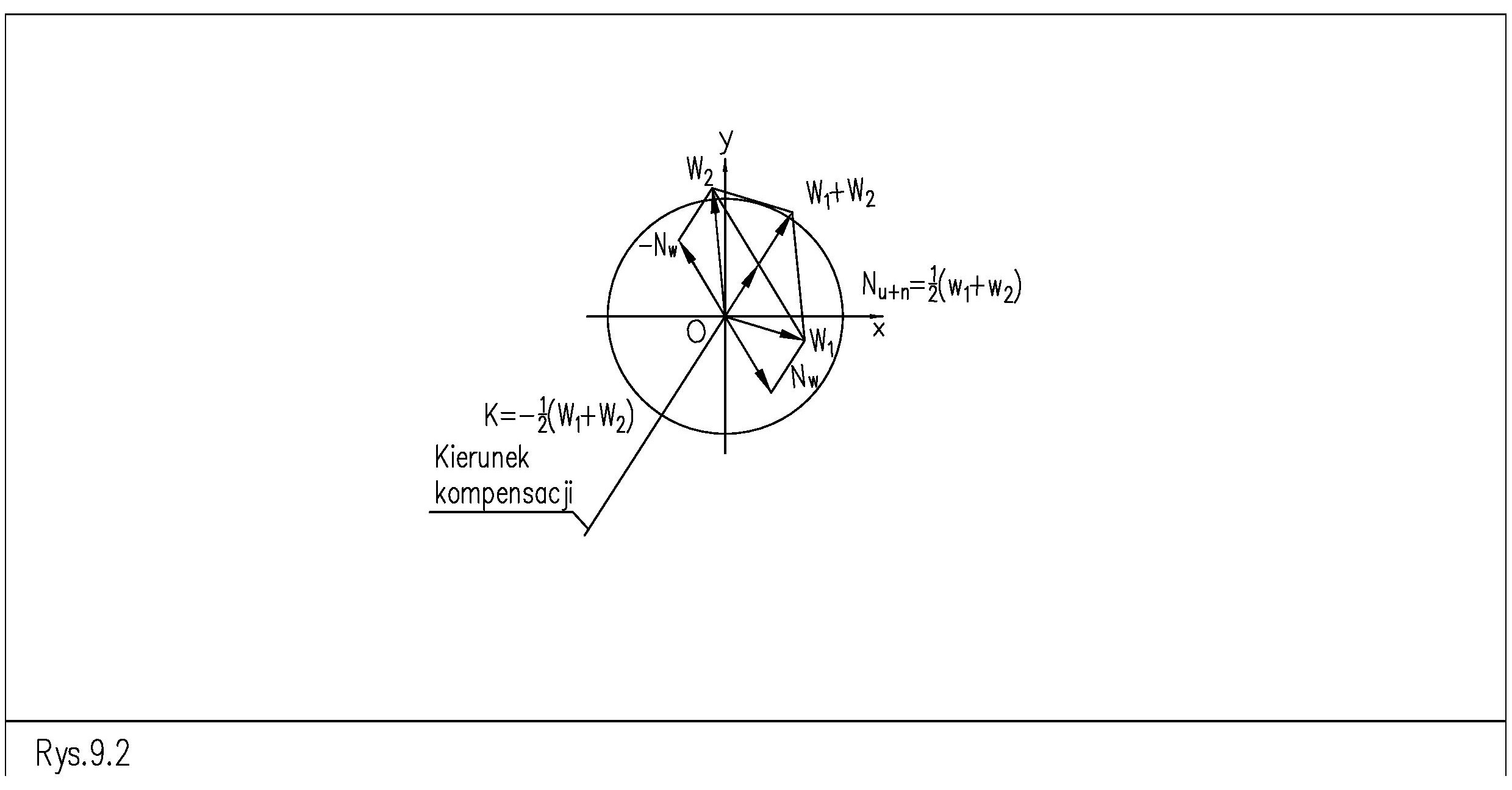
Figure 1 illustrates the indications of the balancer that result from the force interaction of the various components of unbalance. From these, the desire is to eliminate the component: . By changing the mutual angular position of the disc relative to the process shaft, the indication from the disc unbalance (Figure 1 – b, c), changes its position by 180°. The measuring system of the machine records the change in both the value and the position of the angular unbalance of the chuck + the unbalance caused by the off- 𝑁𝑁$ centeredness of the rotor mounting in the chuck , from the value (Figure 2). The harmful unbalance to eliminate in both mounts is constant relative to the angular pitch associated with the measurement system.
𝑊𝑊&to 𝑊𝑊% In Figure 2, it can be seen that, for example, the first indication of the machine (i.e., in the 0° position) is 𝑁𝑁!”# 𝑁𝑁!”# 𝑊𝑊& the sum of the wanted disc unbalance and half of the sum of the indication . Similarly, the signals are summed at a disc position relative to the rotor of 180°. It can be seen from Figure 2 that when a signal with an amplitude of in phase with the angular position of the vector is added to the signal coming from the sensor mounted in the balancer support, the interference signal will be balanced.
% (𝑊𝑊& + 𝑊𝑊%)
& −0.5(𝑊𝑊& + 𝑊𝑊%)
𝑁𝑁!”# Multiple compensations can be successively performed to enhance balancing results. The compensating weight should decrease with each iteration.
Summary
- The operator receives a calculated compensating weight (based on the mounting diameter) and its corresponding angular position on the fixture. The resulting inertial force counteracts the imbalance force .
- 𝑁𝑁!”#
- The operator can add a sinusoidal signal to the measurement path, adjusted in amplitude and phase to null the imbalance signal 𝑁𝑁!”#
- Irregular, random components, such as those caused by random eccentricity within the clearance, are not eliminated by compensation.
- K𝑁𝑁!”#..