Generally, a rigid rotor’s movement is primarily limited to what its ties allow. However, the rotor can move in interesting ways with the freedoms remaining.
The elements of motion to consider are rotation containing two components and transverse vibration also containing two components.
A rotor built in a rotating machine, in its own bearings, moves during rotation in such a way that two points, located on the axis of rotation (e.g. in the plane of the bearings), make motions along ellipses or circles. In order to determine this motion, two sets of data, derived from measurements, would have to be taken at each pivot of the rotor.
Measuring rotor motion in its own bearings
Balancing the rotor in its own bearings, we take measurements in the chosen direction at two locations offset from each other along the axis of rotation. Using directional vibration sensors, we perform signal filtering by measuring its component acting in the selected direction. This component should have a harmonic waveform, but it is only close to harmonic because it contains a lot of interference. In the machine, the interference comes from the various components that are excited to move. Therefore, a useful signal is separated from this component using an electronic circuit with high filtering qualities. The filtering method is specific to balancing machines, as it adapts to the instantaneous rotor speed and does not lose any of the relevant information about the instantaneous rotor position (including angular). The useful signal obtained has a frequency corresponding to the rotor speed and a harmonic waveform.
In the following text, the second type of filtering will be deliberately omitted for simplicity of description. Nevertheless, it is always used.
This is the course of vibration, so selected vibration parameters are measured. Measurement of unbalance is indirect. This means that the value and angular position of the unbalance can be deduced from characteristics of the rotor motion other than the forces originating directly from the unbalance. Figuratively speaking, we can say that the rotor support system “turns forces into motion.”
Knowing how rotors behave on rotation makes it easier to draw correct conclusions from such measurements.
Two families of balancing machines: soft and hard
Balancing rotors on stationary balancing machines can be done in two ways that have become common, over time, in the following order:
a) on supercritical balancers, commonly referred to as “soft” balancers
b) on subcritical balancers, commonly referred to as “hard” balancers.
On supercritical balancers, the way to look for unbalance is similar to balancing its own bearings. There we measure the movement and look for the forces that cause this movement.
On subcritical balancing machines, the ties only allow the rotor to rotate, so inertia forces from unbalance alone are measured.
Balancing on supercritical balancing machines
Balancing on supercritical balancing machines In order to understand the process of finding the position and values of the excess masses (uncompensated on the opposite cylinder face of the rotor by another mass) giving unbalance, it is necessary to analyze the oscillating motion of a system with two degrees of freedom.
Designers of balancing machines have simplified the method of data acquisition in that they have given the rotor such ties, at support points, that force it to move in a plane, usually horizontally. Motion in the plane is a motion with two degrees of freedom (we do not include rotation). This number of degrees of freedom is enough to find both components of unbalance. Balancers are called supercritical because the support stiffness in the horizontal is so small that even with few rotations the rotor is above resonance.
By this, the first filtering of the signal, which we call mechanical, is performed by the support elements. The cleaning of the harmonic component from interference is carried out during balancing in the eigenmodes of bearings, that is, with the help of an electronic system.
Eigenmodes and components of unbalance
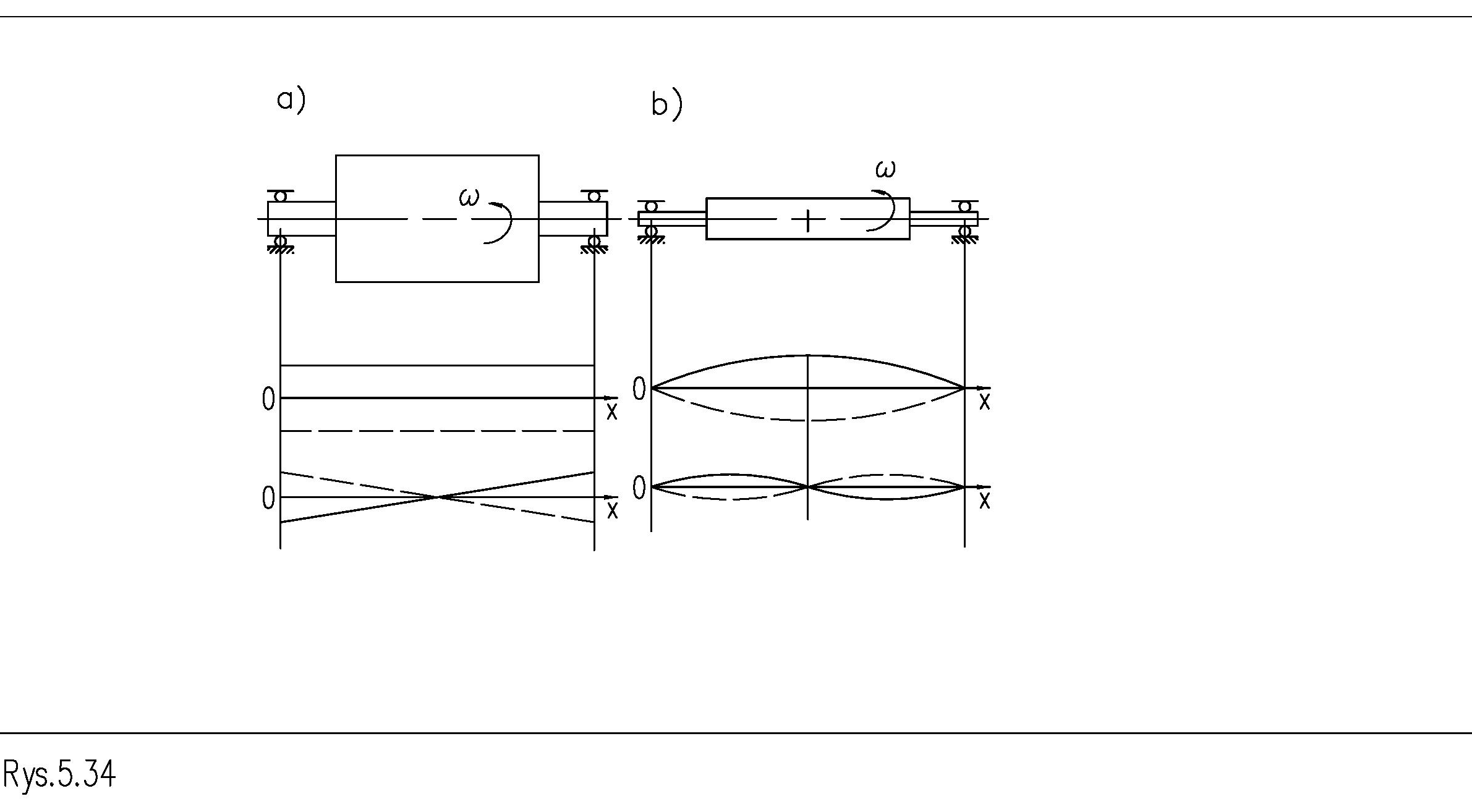
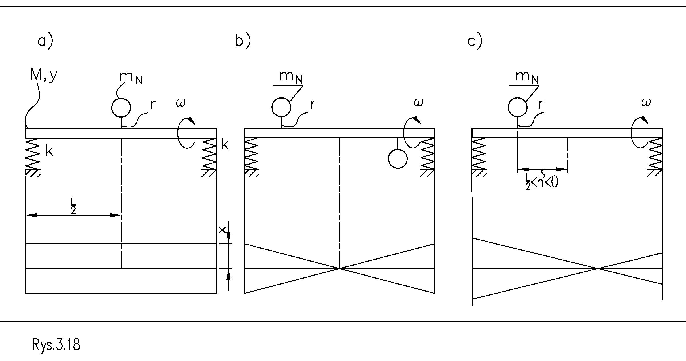
Figure 1 shows what motions can be performed by a rigid, perfectly symmetrical rotor seated on a supercritical balancer. These motions can be:
a) linear and parallel to the axis of rotation
b) angular and taking place, for example, in the horizontal plane.
Each of the aforementioned motions are called an eigen character. Rigid rotors do not exhibit other eigenmodes.
Each of these motions is caused by a different forcing. The linear one is caused by a force from an unbalance. Such unbalance is commonly called static. Angular is known as a moment from unbalance. These are commonly called dynamic. If the rotor is loaded with both components of unbalance, it performs both movements simultaneously.
Notwithstanding the above statement, it should also be noted that motion is the sum of two eigenmodes shown in Figure 1. Hence, the amplitude and phase measured by the sensors are established as the sum of the two components. The summation of the motions can result in different values that fall within a large range of variation. Figure 2. Shows schematically the components of unbalance.
Figure 2 shows components of rotor motion caused by unbalance components:
a) linear caused by static load
b) angular caused by dynamic load
c) mixed caused by both components The measurement occurs once per revolution and always at an identical angular position of the rotor relative to the blade. By this, a rotor moving in a rotary motion is “seen” by the balancer as not rotating. The dynamic phenomenon is observed as kinetostatic.
The method and timing of the measurement is provided by appropriately constructed mechanical and electronic systems. Vibration sensors, fixed in the supports of the balancers, measure the sum of both movements performed in the direction of the axis and action of the sensors.
The operation of supercritical balancers differs from subcritical balancers in that during measurements the rotor performs horizontal reciprocating motions in addition to the rotary one. The reciprocating motions induce additional inertial forces in the rotor mass from the entire mass. These forces are disturbances and the above statement has implications.
Due to the complexity of the problem, identification is done not only at the locations and common direction of vibration sensors but also at a specific rotational speed. It can even be said that full analytical identification of changes in inertia forces from the entire rotor mass are practically incalculable. This is because it depends not only on the mass but also on one of the mass moments of inertia. This makes it impossible to decouple the test planes from the correction planes on the rotor. Correction must take place where the test weights were hung and where partial identification was performed.
If the measurement results include both the effects of rotating inertia forces from unbalance and stationary relative to the spur from the entire rotor mass, it means that:
a) two rotors, having the same mass, loaded with identical unbalance, but having different shapes, will behave differently on the balancing machine at the same revolutions
b) a given rotor will not behave dynamically and identically when rotations change although the unbalance of a rigid rotor is constant; depending on the amount and distribution of the rotor mass, the amplitude of vibrations measured in the selected direction on the rotor supports will change.
In addition (as will be shown below), the angular alignment between the force from unbalance and the movement of the rotor changes. This should be understood in the sense that the rotor, in the same phases of vibration displacement (for example, at maximum swing), is at a different angle of rotation relative to the blade and at different rotational speeds. So, this means that, in addition to the rotational movement, the rotor performs an additional rotation of a small angle one time per change of rotational speed.
Therefore, each process of balancing another rotor, on a supercritical balancing machine, is preceded by the so-called partial dynamic identification of the system’s rotor and supports. With this identification, calibration coefficients are found, as well as the values and actual seating angles of the correction weights.
Rotors on rotation, seated on supercritical balancers, behave specifically. We will trace this behavior.

A model system: unbalanced disc on an elastic support
Figure 3 shows a system: a rotor of mass M + a support having stiffness k and viscous damping c. Let’s analyze the behavior of such a system.
The superimposition of susceptible bonds, as in Figure 3, filters the component of motion in the direction of choice. Sensor signals on balancers are similarly filtered. Sensors there extract a component, acting in a certain direction, from the signal rotating with the rotor. The extracted component has a harmonic waveform. Thus, Figure 3 shows the state after filtering out the useful signal.
Restriction of the mass motion by imposing ties on the point 0, in the form of a slider, to motion along a straight line in the x-direction does not change the established directions of the forces occurring at the point 0. The motion of the disc in the direction of the x-axis takes the form of a single harmonic component.
The centrifugal force pushing the movement has a value:
𝐹𝐹⃗! = 𝑚𝑚! ∙𝜔𝜔” ∙𝑟𝑟⃗ It spins with the disc and excess mass with angular velocity ω maintaining the direction of the radius on which it is seated. We note that the value of the inertia force increases exponentially with the change in rotational speed. Under the action of this force, the rotor behaves specifically. Figure 4 shows the waveforms of the inertia force from unbalance and mass motion. It can be seen that the force precedes the motion by an angle φ in the rotor’s rotation. The value of this angle depends on both the applied rotational speed, stiffness and damping.
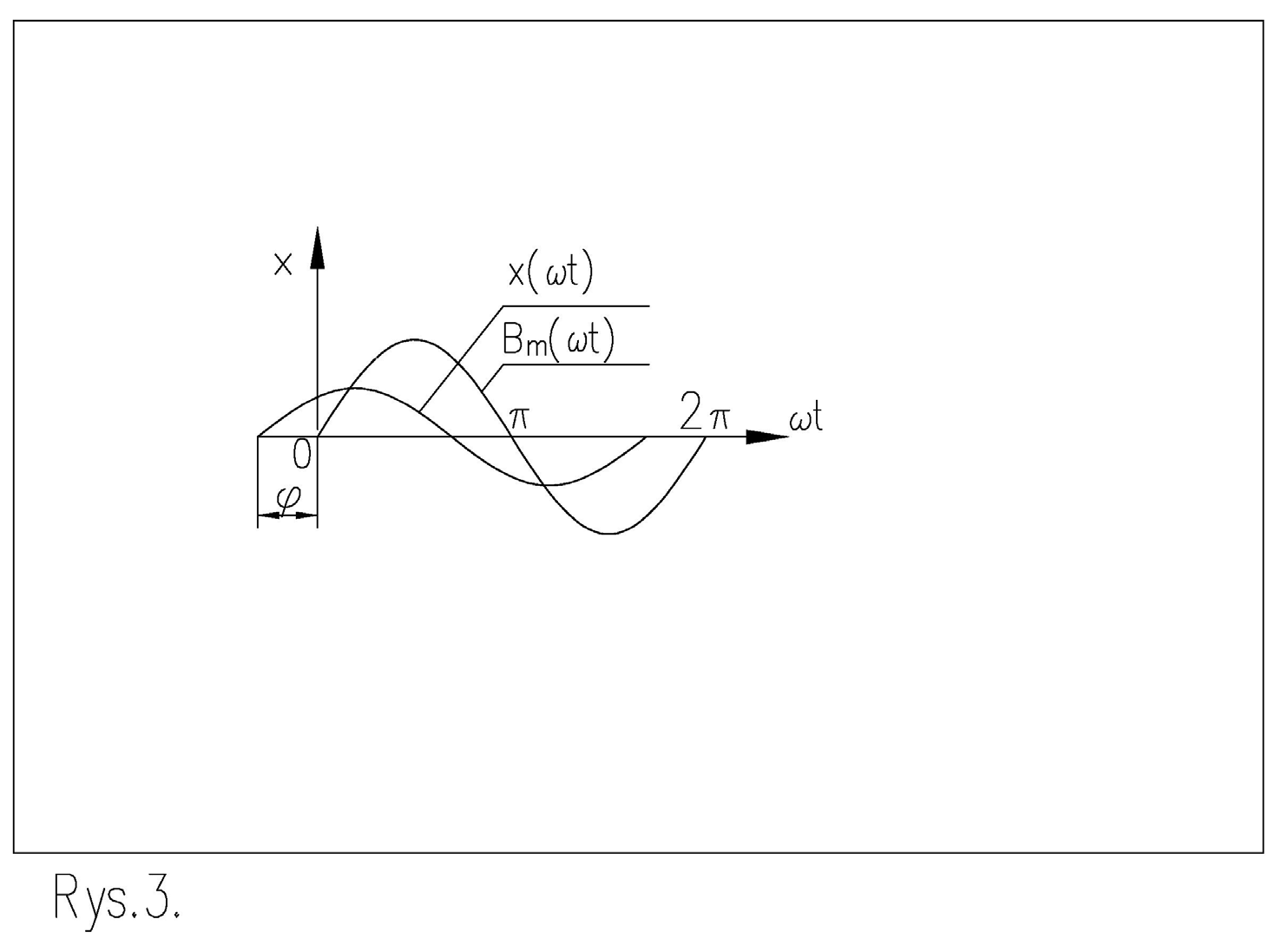
Figure 5 shows the reciprocal arrangement of forces at point 0 on the phase plane. The vertical axis shows the forces that depend on the displacement of point 0, and the horizontal axis shows the forces that depend on the velocity of displacement within the center of the disc. On the rotor, all the forces including the force from the Bₘ, rotate at a rotational speed ω. Their mutual angular alignment (for a particular rotor with an invariant foundation on the spur) does not change over time, for the selected rotational speed.
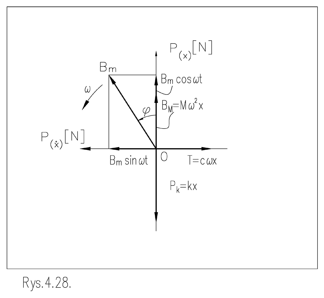
When the velocity changes, the mutual alignment changes depending on the amount of damping. In the figure, you can see that the forces balance each other in the direction of the vertical axis P(ẋ) as well as in the direction of the horizontal axis P(x). The horizontal component of the inertia force Bₘ balances the force from damping. The vertical component assists the inertia force coming from the mass of the disc M in order to balance the force coming from the stiffness Pk. Such a system of forces, in which the angle φ<π 2, occurs for subcritical speeds, occurs when the inertia force does not have a large amplitude and the deflection is significant. This system of forces is not the only system. Of all the others, two more can be distinguished:
a) in which the angle b) in which the Case a) occurs when the frequency ω resulting from the rotational speed of the disc takes a value corresponding to the so-called eigenfrequency, most often denoted by the symbol ωₙ. The system is then in so-called resonance, in which the amplitude of motion increases. As a result, all forces increase.
Case b) occurs when the frequency ω resulting from the rotational speed of the disc takes a value higher than the eigenfrequency.
𝜑𝜑= % “
𝜑𝜑> % “
Resonance and inertial forcing
At resonance, the excursion in motion is the greatest when the force from damping reaches a large value. After resonance, the inertia force increases. Its amplitude depends on the frequency ω in the second power. Therefore, the force from unbalance supports the action of the force from stiffness, together opposing the force of inertia increasing in the second power.
The angle of deflection by the inertia force φ takes values close to 180° on supercritical balancers. When balancing in self-bearing, they can cover a larger range of variation.
Unbalance is a forcing on the rotor called inertial forcing. The name comes from the inertia force caused by rotation. The value of the force from unbalance depends on the frequency resulting from rotation. This dependence causes the system to behave specifically at high rotations, that is, above resonance.
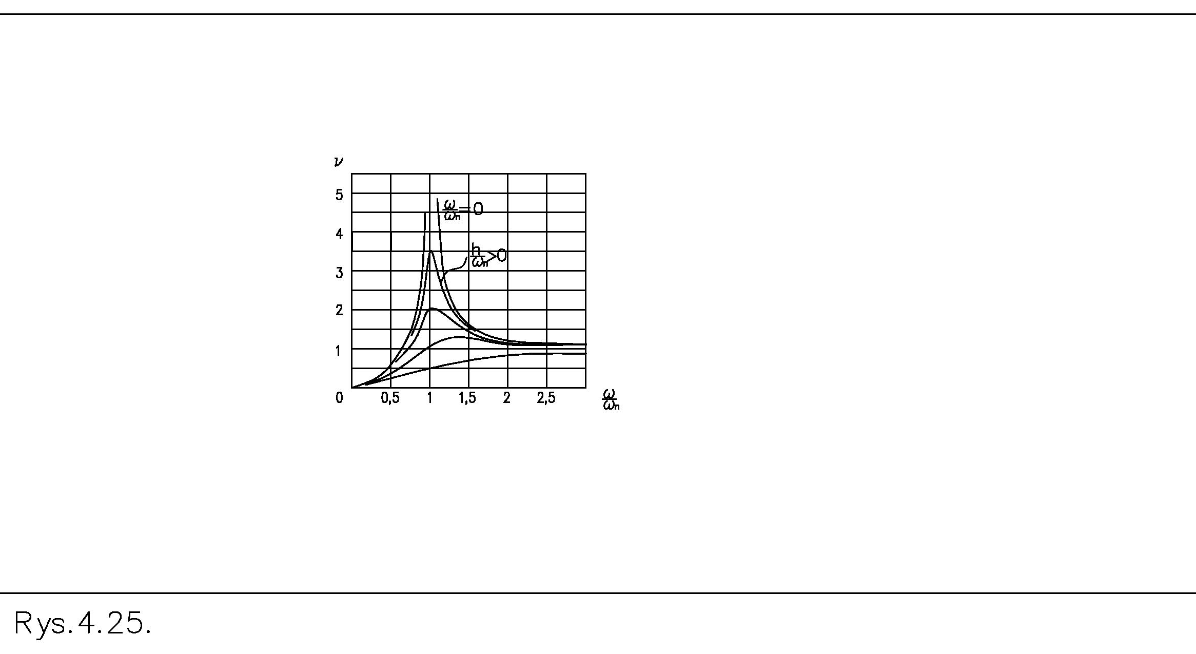
An important property of the system is shown by the multiplication factor defined as follows:
𝑚𝑚𝑚𝑚𝑚𝑚𝑚𝑚𝑚𝑚𝑚𝑚𝑚𝑚 𝑐𝑐𝑐𝑐𝑐𝑐𝑐𝑐𝑐𝑐𝑐𝑐 𝑏𝑏𝑏𝑏 𝑢𝑢𝑢𝑢𝑢𝑢𝑢𝑢𝑢𝑢𝑢𝑢𝑢𝑢𝑢𝑢𝑢𝑢 = |𝑥𝑥| (2) 𝜈𝜈= ℎ𝑎𝑎𝑎𝑎𝑎𝑎 𝑜𝑜𝑜𝑜 𝑡𝑡ℎ𝑒𝑒 𝑠𝑠𝑠𝑠𝑠𝑠𝑠𝑠𝑠𝑠 𝑎𝑎𝑎𝑎𝑎𝑎𝑎𝑎𝑎𝑎𝑎𝑎𝑎𝑎𝑎𝑎𝑎𝑎 The upper limit of the ratio is:
𝑒𝑒 (3) 𝑙𝑙𝑙𝑙𝑙𝑙!→# :
& ; = 1 |%| The course of the value of the multiplication factor, or amplitude of motion, depending on the frequency ω, is shown in the amplitude characteristic in Figure 6. It shows that for high speeds the amplitude of motion is equal to the eccentricity of the disc e. The phase diagram shows that for these speeds the angle φ takes values close to π. As a result, this means that the displacement is in counter phase. The greater the damping c, the smoother the changes in amplitude and phase occur when the speed is changed.
The above property of the rotating mass has its consequences in the motion of a rotor having length L. It allows the formation of successive eigenmodes of deflection in prone rotors. This problem will be recognized separately when analyzing the behavior of limber rotors.
Balancing on subcritical balancing machines
When balancing on subcritical balancers, the ties only allow the rotor to rotate. By design, the rotor does vibrate. It performs only rotational motion. If there is an imbalance on the rotor, the inertia forces generated by it act on the support elements. The forces are measured and analyzed.
Such properties are achieved by a sufficiently large support stiffness. It is large enough to make it below resonance at any rotor speed.
A colloquial statement can be recalled here: below resonance, the behavior of the rotor is determined by the support stiffness, and above resonance by the amount of rotor mass and its distribution. Any change in the amount or distribution of mass requires making a new identification. In “soft” balancing machines, each new rotor being balanced, having a different amount of mass and its distribution, will already make different movements regardless of unbalance. So, you can’t use the data from the “old” identification for the “new” rotor.
The search for load therefore requires a new identification.
In “hard” balancing machines, when changing from one rotor to another, the support stiffness does not change. So, you can use the data from the “old”
identification to balance a rotor of a different shape or weight.
In practice, rigid suspensions of support rollers can be reformed. Their deformations are small enough that their influence can be minimized in the calculation of unbalances using fixed coefficients for different rotations, depending only on the rotor mass. These can be, for example, three sets of coefficients valid for the entire range of rotations: low, medium, and high rotor mass.
Eliminating the effect of mass quantity and distribution on the forces present in supporting a balanced rotor on rotation, results in new process possibilities in balancing including:
a) decoupling the identification process from the rotor currently being balanced
b) selection of the position of correction planes independently of the position of test planes.
Where do these capabilities come from in subcritical balancers? Only the inertia forces caused by unbalance are a variable load on the rotor support. Changing the rotation causes proportional and predictable changes in the amplitudes of inertia forces. Other inertia forces are absent. Due to the rigidity of the rotor, the mutual alignment of all components of unbalance does not change when the rotation changes. Two very different looking rotors, e.g. a light and a heavy rotor, a slender rotor, and a massive rotor, but all loaded with the same unbalance, will behave identically on this balancing machine. This means that the variation in support load, in both cases, will be identical.
Calibration with a reference rotor
If the identification is not related to the mass and shape of the rotor, the identification process can be performed once, for all rotors, using a reference rotor. The data from the identification should be stored in the machine’s memory as calibration coefficients and used for subsequent balancing. Therefore, these machines are calibrated once by the factory service after assembly on the customer’s shop floor. In practice, changes occur in the foundation and through the attachment of the machine to the foundation during machine operation. Therefore, the best balancing efficiency is ensured by annual service performed by the balancing machine manufacturer’s team.
As a reminder, a supercritical balancer takes measurements when the rotor is always in an identical position. That position is angular with respect to the blade and the inertial forces form a variable system of forces containing components. This includes a constant from the unbalance and a variable from the entire rotor mass.
A subcritical balancer also takes measurements when the rotor is always in an identical angular position relative to the blade, but the inertial forces form an invariant system containing one set of forces – those from unbalance. There is no separation of force and motion since lateral motion does not occur. The invariability of the system consists in the equal dependence, on rotational speed, of all elements of the set and the constancy or zeroing of the angle φ (Figure 6).
On a subcritical balancer, we observe a kinetostatic system of forces containing elements that are variable in a predictable and countable way with a change in rotational speed.
Conclusion
- It is not possible to directly show or measure the angular position of the unbalance on the rotor, using a balancing machine, due to the phase shift between the inertia force from the unbalance and the rotor’s rotational motion, and the summation of motions performed according to several degrees of freedom. One obstacle is the influence of inertia forces generated by the transverse oscillating motion of the rotor. The possibility of identifying the location of excess mass, for example, occurs after a test, using test weights, and performing calculations that consider the response of the rotor to these weights. The use of test weights is not shown in this text.
- A common feature of balancing rotors in own bearings and on supercritical balancers is to perform the so-called limited dynamic identification of the system: rotor + support, using test weights, before each balancing. Such a test is intended to check the behavior of the system: a particular rotor + foundation, under the influence of an external load at, for example, two points and additionally at any point, but in the same direction. The immediate reason for the necessity of the test is the presence of inertia forces from the entire mass of the rotor during the execution of oscillations – independent of the inertia forces from unbalance.
- The main advantage of subcritical balancers, over supercritical balancers, is the ability to use the calibration coefficients obtained during a single identification with a reference rotor to balance other, different rotors. The independence of an unbalance calculation results from the amount and mass distribution of the rotor being balanced, which was achieved by eliminating rotor transverse vibrations on rotation.