Machining methods are constantly improving and, in turn, the experience of designers and manufacturers is expanding. Since assembly methods for rotating assembly components are based on the experience of predecessors, why has the problem of unbalance and minimization of rotor vibration not disappeared?
Among other reasons, because:
a) ISO 21940-11 processes and tolerances for rotors with rigid behavior (PN 93/N-01359 balancing of rigid rotors; determination of permissible residual unbalance) define the values of permissible residual unbalance of rotors with different purposes
b) In parallel with the increasing competition in the market for mechanical-related goods, the requirements for the quality – including the value of residual unbalance – of components and their subcomponents are increasing
c) The general trend toward an increase in the high-speed rotation of rotors continues, which highlights the importance of minimizing their unbalance
In the study, we want to show that the reason for the need for balancing is a specific property of the mass from which rotors are made. We also want to show the importance of the so-called “real axis of rotation.”
The force of inertia and centrifugal forces
In general, while analyzing any physical phenomenon related to the change in motion of a body of any mass, it can be said that mass (when subjected to acceleration) presents a forceful resistance. This resistance is called the force of inertia.
Any element of mass that makes up a rotor is accelerated during rotation if it’s away from the actual axis being rotated. If the rotational motion has a constant velocity, the acceleration has one component with a centripetal direction. Because of the occurrence of this acceleration, centrifugal inertial forces are generated. If they are not compensated, along the length of the rotor, the individual resultant forces oscillate. The uncompensated inertia forces rotate with the rotor following the uncompensated rotating mass. Because the rotor support structures have a certain stiffness, the conditions for vibration are created at these locations. If the rotating machine is not designed to do the work by means of vibrations, they are a disturbance and, among other things, reduce its service life. Hence, technicians have associated vibration with uncompensated mass distribution and defined unbalance. Ascential Technologies builds machines to measure and minimize this unbalance.
The principal, central axis of inertia
At the outset, the question should be posed around what axis the mass (i.e., a rotor of any shape) would want to spin if it could be rotated in space by pure torque and without support (i.e., in so-called free motion)?
The answer is that free motion would take place around the main, central axis of inertia. This axis passes through the center of mass of the rotor and is directed so that the unit masses are in equilibrium for all planes that are perpendicular to this axis. This means that, in this direction, the mass distribution of the rotor is circularly symmetric along its entire length. In practice, we approach such a situation at the end of effective balancing of the so-called low- and high-speed rotor. If the rotor is rigid, then the problem simplifies to resultants. This means that in order to achieve circular symmetry, low-speed balancing is sufficient where there are only two planes in which correction masses must be applied to counteract the lack of symmetry along the entire length of the rotor.
An illustration: the cannon projectile
This situation is correctly illustrated by the flight of a cannon projectile. The flight can be divided into two stages: the first ends when it leaves the cannon barrel, the second when it hits an obstacle. In the first stage, the inner surface of the barrel is a bond for the projectile, forcing it to align on rotation in accordance with the geometric axis. If its mass is distributed non-coaxially along its entire length, the bonds prevent the projectile from rotating around its main and central axis of inertia. Because of this, the rotating projectile impacts the barrel by centrifugal forces. After leaving the barrel (and after its own vibrations are damped around an axis perpendicular to its trajectory), the projectile continues to fly about its main and central axis of inertia. Its forward cone curves a helical line in space. The relative inclination of the two axes (geometric that is real and main/central) can be calculated.
Geometric axis versus the actual axis of rotation
In a perfectly straight and circularly symmetrical cylinder, with journals ended with perpendicular planes, the main and central axes of inertia coincide with the geometric axis. If it were seated on the roller bearings of the balancer, the actual axis of rotation would coincide with the geometric axis. If during the process of manufacturing the rotor, we milled grooves at the ends of such shaft for keyways, and then mounted eccentricity and angular errors on it, then other components of the assembly (e.g. the main and central axis of inertia of the assembly) would not coincide with its geometric axis. The free rotational motion of this assembly would take place around the summation, which is another central and principal axis of inertia. This is because it does not coincide with the axis of a circularly symmetrical and straight shaft.
When the mass is rotating but there is no support, unbalance does not appear. When the roller bearings, which are ties for the whole assembly, are mounted on the shaft the rotational motion of the total mass of the assembly will be forced by the bearings around a different axis of rotation called the actual axis.
Now the conditions have come for defining and measuring unbalance.
Unbalance in assembled systems
It is correct to say that mechanical systems that cooperate in rotary motion are usually designed so that their axes of symmetry, after assembly, should also coincide. As a result of trace shape and assembly errors, the actual common axis of rotation of the system most often does not coincide with any axis of a component element.
Therefore, the common center of gravity of all components of a rotating system does not lie on the actual axis of rotation. Some components may also be attached obliquely, that is, with an angular error. By this, the main mass axis of inertia of the entire rotor lies obliquely with respect to the actual axis of rotation. Such an alignment of the two axes (the main central inertia and the actual rotational axis) with respect to each other is the source of the motion forcing and additional forces occurring at the support points of the rotor. This forcing is specific to the extent that the amplitudes of the forces grow with increasing rotation of the rigid rotor and a constant direction relative to the rotor.
Worked example: motor shaft and clutch disc
To illustrate the fact that the assembly of correctly made components can introduce unbalance, let’s examine the following practical example.
Figure 1 shows the connection of an electric motor shaft to a clutch disk. The end of the motor shaft shows radial runout W.
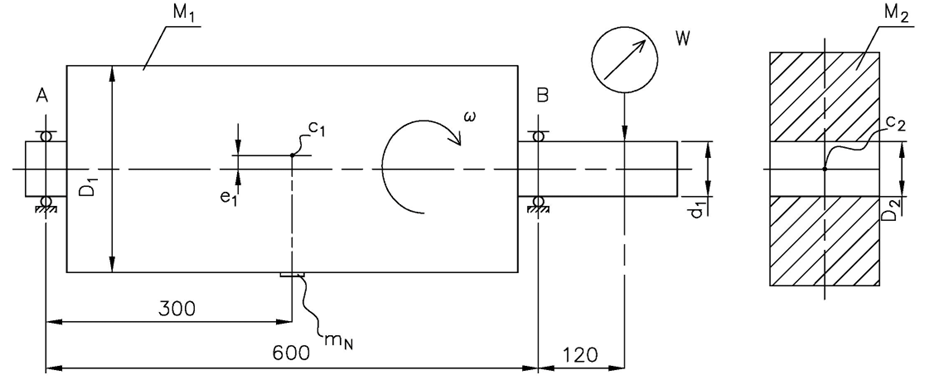
The clutch disc can be fixed on the rotor arbitrarily, but within its clearance, while the clearance can be cleared at any random angle in the plane perpendicular to the axis of rotation. According to the rules, we assume the worst case: the runout of the shaft and the maximum deviation of the hole execution add up in the same direction. The rotor, in the planes in which the bearings are mounted, rotates along the actual axis of rotation 1. The geometric axis of the end of the rotor shaft is axis 3. The main, central axis of inertia of the coupling disc, along with the center of gravity c2, is axis 2.
Input data:
d1=34,984 mm (diameter of the rotor shaft), D2=35H7 mm (diameter of the bore made in the clutch disc), W=24 μm (measured radial runout on the rotor shaft).
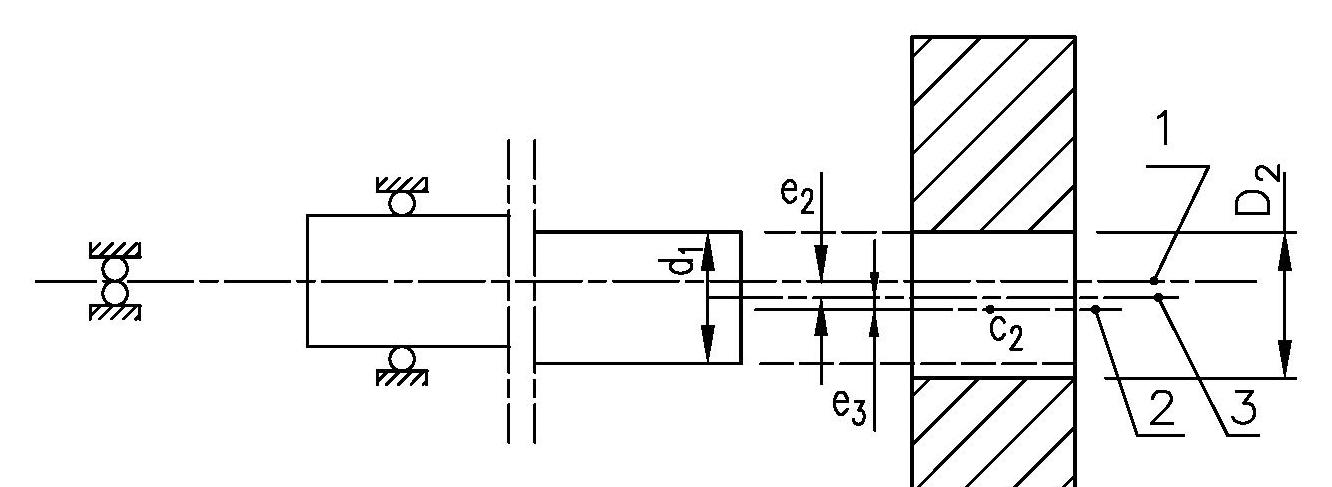
Already in such an assembly, unbalance can occur. The rotor runs in its bearings during measurements.
Summary
- Centrifugal inertial forces act on each mass particle of a rigid rotor during its rotation and increase with rotation. Due to the circular symmetry of the rotor, the force on one side is compensated by a force acting in the opposite direction. In any rotor, it is possible to determine such an axis with respect to which all these forces are compensated in pairs. This is the principal and central axis of inertia. If the rotation takes place around this axis, no reaction forces are generated in the support of the rotor.
- By attaching rolling bearings, for example, to the shaft of any rotating assembly, we establish the rotor’s rotational motion around the axis that will form according to the design of the bearings. The bearings will force the rotational motion in space regardless of the rotor design, with exact motion dependent on the bearing design. The so-called real axis of rotation will be formed.
- The bearing is a bond for the rotor. If the actual axis of rotation does not coincide with the main and central axes, an unbalance is created. The value and direction of this unbalance depends on the mutual arrangement in space of the actual axis of rotation and the main, central axis of inertia.