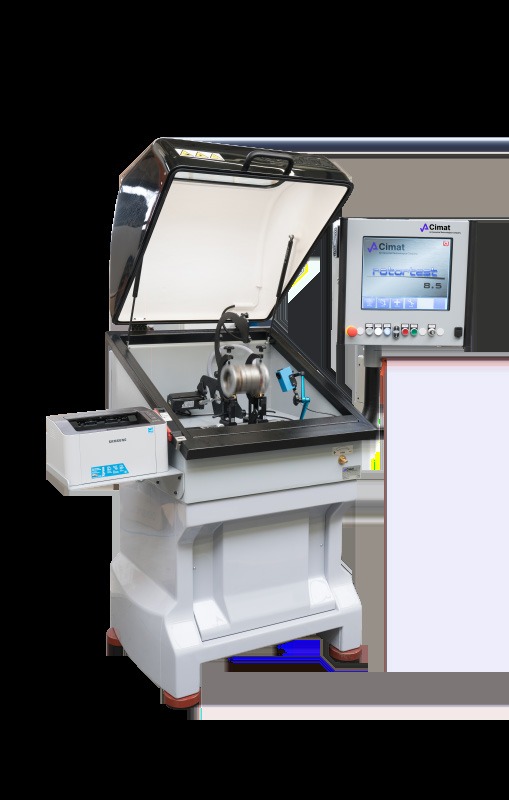
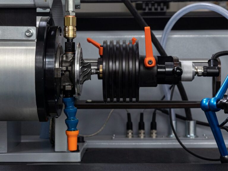
The most important technological elements of balancing machines include:
a) shafts, which are part of universal, horizontal balancing machines, and
b) adapters, which are holders for rotors mounted on spindle heads and are mainly found in the equipment of vertical balancing machines.
The quality of their workmanship determines the adequacy of the machine’s readings. Their task is to mount the balanced rotor:
a) as close as possible to the actual axis of rotation;
b) in a repeatable manner with respect to the radial and angular runout of the rotor, in relation to the actual axis of rotation.
What are technological shafts?
What are technological shafts?
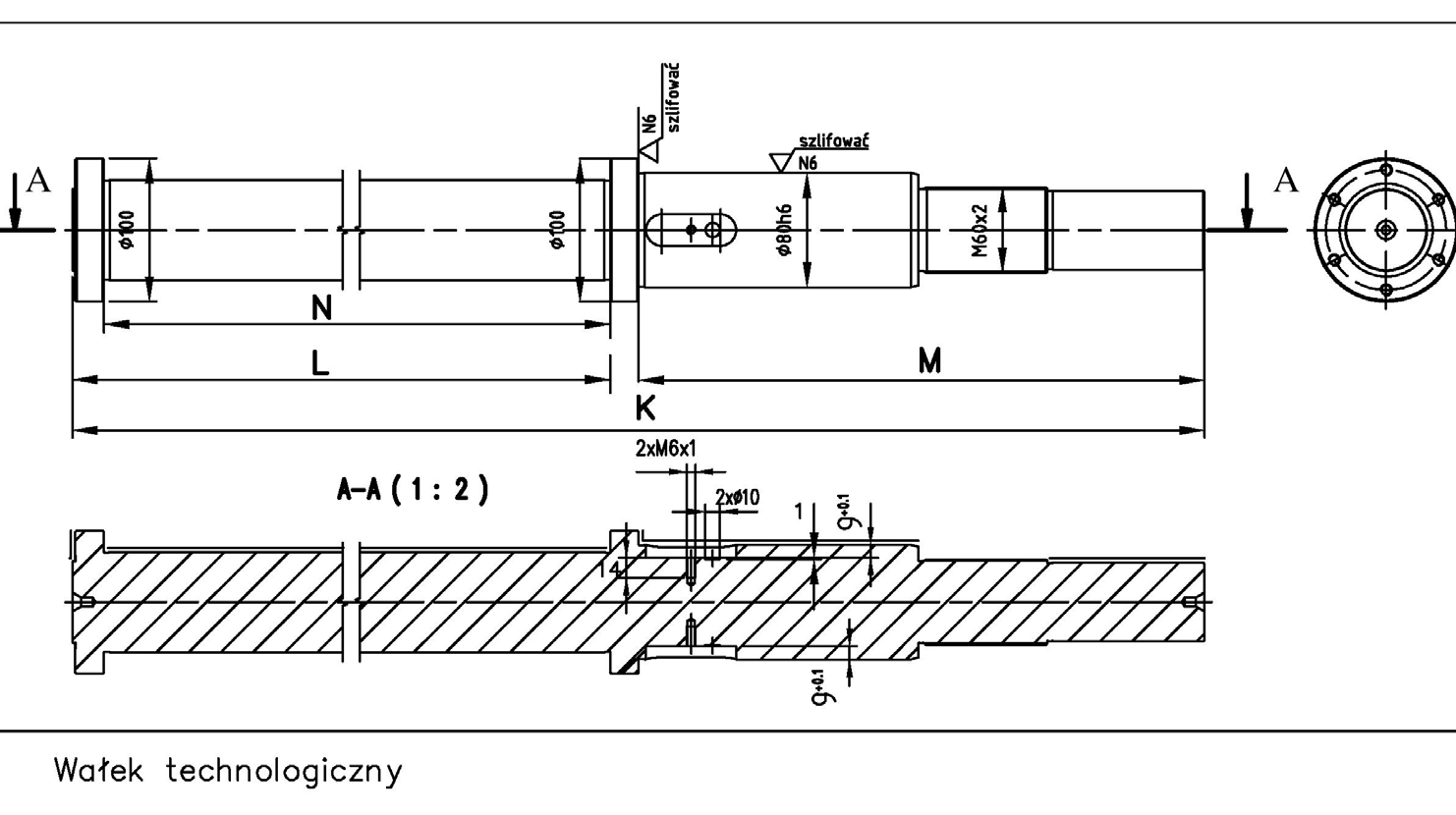
A technological shaft is a fundamental component of universal, horizontal balancing machines, used to mount “disc” type rotors. Practical experience shows that shafts, varying in manufacturing quality, can be a source of measurement errors. The quality of a given shaft is determined by the details of its construction. One of the design features is milled grooves, made to simultaneously mount a spline and half-spline, on the diameter where the balanced disc is mounted. The grooves are angularly offset from each other and the shaft manufacturer must ensure their precise angular positioning and maintain uniform geometric dimensions. An angular error or the removal of an uneven amount of shaft material results in a reduction in the effectiveness of compensating for harmful imbalance.
The shaft should have hardened surfaces that serve as supports on the support rollers and at the disc mounting point, and a “soft” center. Additionally, it should be free of residual stresses, which cause the shaft to bend over time due to stress relaxation.
Considering the value of the smallest residual imbalance obtained, we conclude that the shaft must allow for:
a) achieving a certain repeatability of imbalance measurement results b) introducing a minimal component of additional imbalance, which is a disturbance to the correct result.
The repeatability of results is significant in the sense that it is also the insurmountable limit of balancing accuracy.
Each subsequent measurement is burdened with systematic and random errors. Balancing machines have internal procedures to eliminate systematic errors. They compensate for imbalance resulting from eccentricity of mounting and imbalance of the fixture.
After eliminating systematic errors, the machine indicates a new location for mounting the correction weights. If, after mounting them on the rotor, the amplitude of the readings is not smaller, it means that random errors also occur. Theoretically, it is not possible to achieve a smaller residual imbalance than the imbalance resulting from the random incorrect mounting relative to the axis of rotation. One of the reasons for such a situation may be the clearance occurring at the mounting point of the balanced rotor on the technological shaft. The clearance can be eliminated in any direction of the shaft before tightening with a mounting nut. If the cause of the repeatability is clearance, it is possible to improve the result by eliminating the clearance in the same direction before performing:
a) a repeated procedure of compensating for the rotor mounting error,
b) the final measurement of the imbalance, taking into account the new compensation.
Eliminating the clearance removes it from the set of random causes of mounting errors. This procedure can be applied when balancing a single rotor. When applied in a series, it will cause the mounting errors to depend on half the difference in the diameter of the hole in the next rotor in relation to the rotor with which the compensation was performed. Usually, such a method improves balancing results, especially for rotors made in a low accuracy class.
When balancing, even a minimal bend in the technological shaft can be observed. The result of the bend is a runout of the cylindrical surface intended for rotor mounting relative to the actual axis of rotation. This axis is determined by the geometric centers of the circles formed on the surfaces of both journals, which are located at the shaft support points. Typically, the shaft bends due to the relaxation of post-hardening stresses. Radial runout of the cylindrical surfaces may also occur due to grinding errors.
Both shape errors of the shaft cause additional, harmful imbalance. It results from the eccentricity of the rotor mounting relative to the actual axis of rotation. The radius of curvature of the shaft is large. If the shaft were a component of any mechanism, the curvature would probably not be noticeable. The shaft, together with the rotor, is usually supported on the balancing machine and wider than any rotor rotating in its bearings in the working machine. As a result, the runout is greater.
The error in indicating the imbalance, both in terms of the location and value of the mass, is also related to the quality of the journal surfaces of the rotor at the point of contact with the balancing machine support rollers. Both mechanical damage in the form of dents and lack of circularity, as well as insufficient surface smoothness, are sources of additional signals. They are generated in the vibration sensors in the machine supports. These signals are difficult to eliminate by the electronic filter system. Each of these errors have a different image observed on the oscilloscope screen.
a) Mechanical damage to the surfaces and lack of circularity of the journals force an additional kinematic movement of the balanced rotor, which causes additional inertial forces on the rotor and, consequently, generates electrical signals containing many components. Some components are sufficiently distant from the useful signal and are attenuated by the electronic filter system. Other signals practically coincide with the useful signal (have the same frequency). These signals are not attenuated. Local damages act like impacts on the rotor, and the level of electrical signals caused by the impact is similar to a unit step with a dense spectrum, from which one of the components is added to the useful signal.
b) Insufficient surface smoothness increases the level of noise of the signal from vibration sensors at practically any frequency. The average noise level at the end of balancing, in practice, can be many orders of magnitude greater than the level of the useful signal. It includes signals equal to the frequency of the useful signal and therefore are not filtered.
The influence of the background on the value of the residual imbalance is not as significant as the lack of circularity or damage to the journal. It should be noted that the quality of the shaft becomes more important as the residual imbalance on the rotor decreases. At the beginning of balancing, with a (large) initial imbalance, the balancing process is fundamentally fast at converging. Imperfections in the shaft’s workmanship become apparent after achieving a small value of imbalance and the convergence rate decreases.
The perfection of the measuring devices of the machine is unable to overcome the imperfections of the shaft’s workmanship. To show the significance and difficulty of eliminating errors, let us consider the implementation of rotor balancing using a selected shaft.
Problem 1: centering accuracy for an accuracy class
Problem 1.
Given:
𝑀𝑀= 10 𝑘𝑘𝑘𝑘 – mass of the balanced rotor 𝑛𝑛= 2500 𝑜𝑜𝑜𝑜𝑜𝑜./𝑚𝑚𝑚𝑚𝑚𝑚 – rotation of the balanced rotor 𝑟𝑟= 150 𝑚𝑚𝑚𝑚 – radius of the rotor 𝐺𝐺 = 2.5 – required balancing accuracy class.
Calculate the centering accuracy of the rotor to achieve the required balancing accuracy class. In the first step, we determine the value of the allowable residual imbalance:
𝑚𝑚= 30𝑚𝑚𝑚𝑚 𝜋𝜋𝜋𝜋𝜋𝜋= 30 ∙10000 ∙2.5 ∙0.8 3.14 ∙150 ∙2500 = 0.5095 𝑔𝑔. 𝑀𝑚𝑒𝑚𝑚𝑚𝜋𝜋 We will use the static moment of both masses (𝑀𝑀+ 𝑚𝑚)𝑒𝑒= 𝑚𝑚𝑚𝑚, 𝑀𝑚𝑒𝑚𝑚𝑚 𝑀𝑀≫𝑚𝑚, Given that to:
𝑒𝑒= 𝑚𝑚𝑚𝑚 𝑀𝑀= 0.5095 ∙150 25000 = 0.00382 𝑚𝑚𝑚𝑚= 3.056 𝜇𝜇𝜇𝜇, Where “e” is the eccentricity of the rotor, or specific unbalance, per unit mass.
The value of the allowable eccentricity is not easy to obtain in large batches. The result indicates the difficulty of having the balancer operator obtain it at each mounting.
Finding:
If we want to be certain that the residual imbalance achieved meets the required accuracy class, it is not sufficient to simply read the final balancing result on the machine. The accuracy of this result must be verified. The machine does not distinguish between imbalance belonging to the fixture (in this case, the technological shaft), resulting from possible eccentric mounting of the rotor in the fixture or imbalance of the shaft itself from the imbalance belonging to the balanced rotor.
Therefore, the following two steps must be performed sequentially:
1) using a reference rotor, verify the adequacy of the machine’s indications; the indicated imbalance must correspond to the imbalance that is characteristic of the given reference rotor.
2) by rotating the balanced rotor relative to the shaft, which serves as a fixture for the rotor, check the quality of compensation for the fixture imbalance and eccentricity of the rotor mounting (the compensation process also does not distinguish between shaft imbalance and eccentricity of the rotor mounting on the shaft) with proper compensation. The value of the indicated correction weight does not change, but the indicated angle for its mounting changes in a tracking manner with the rotation of the rotor relative to the fixture.
Practice shows that with a well- calibrated machine and properly performed compensation, a margin of about 20% of the tolerance field should be allowed for unidentified errors occurring during the physical correction of the imbalance. This usually involves drilling, milling holes, or welding correction weights. Therefore, it is necessary to achieve 80% of the value of the allowable residual imbalance. This will guarantee that the balancing protocol confirms reality.
The following design solutions enable achieving the appropriate balancing accuracy class:
a) the fit of the rotor on the shaft should prevent the kinematic pair from being assembled by hand, but require the use of a hand press.
b) the technological shaft should be prepared for mechanical compensation of harmful imbalance — both by the possibility of its mounting in positions relative to the cardan drive, and by the possibility of relative mounting of the balanced rotor to the shaft in positions. Because balancing machines produced after 2005 allow relative rotation also at other angle values, it is necessary to make a half-spline, which is fixed each time on the opposite side, in relation to the spline.
c) in production conditions, when the shaft is used multiple times, the shaft material cannot be hardened too deeply due to hardening stresses that relax over a long period of time. Through relaxation, the shaft may bend differently.
A small allowable eccentricity of the balanced rotor mounting on the technological shaft is difficult to achieve using conventional mechanical machining. Therefore, the experience of technologists involved in the preparation of technological shaft production play an important role in the application of additional technological processes.
A separate problem, when using a technological shaft, are the requirements that arise from the design or operational documentation of the balanced rotor on the one hand, and the possibilities of correcting the mass distribution on the other. In the case of angular runout, it is often impossible to correct the mass distribution using two weights that would compensate for the moment of inertia forces. However, this imbalance must be shown by the machine. Therefore, balancing must be performed simultaneously in two measurement planes. This requirement is another indication of the shape of the technological shaft. In particular, a shaft mounted on a supercritical machine should have an additional thin disc, with a small mass, which will allow for precise two-plane calibration.
To obtain a good measurement, the signals in both sensors in the supports should have amplitudes of the same order. Mounting the balanced rotor near one of the supports causes an imbalance of the signals generated in the supports. In extreme cases, when the rotor is mounted in the immediate vicinity of one of the support rollers, the signal in the opposite support is residual. The balancing result calculated from such signals may be subject to an unacceptable error.
What are adapters?
What are adapters?
Adapters are a fundamental equipment part of balancing machines with a vertical balancing axis. In vertical balancing machines, the adapter, together with the spindle, replaces the technological shaft.
Adapters used for balancing “disc”
rotors can be divided into those that center the rotor using:
a) the central hole of the rotor,
b) the external surface (usually cylindrical).
Adapters should be constructed to allow the mounting of rotors while maintaining minimal errors related to:
a) centering to the axis of the head on the spindle,
b) perpendicular support in relation to the axis of rotation.
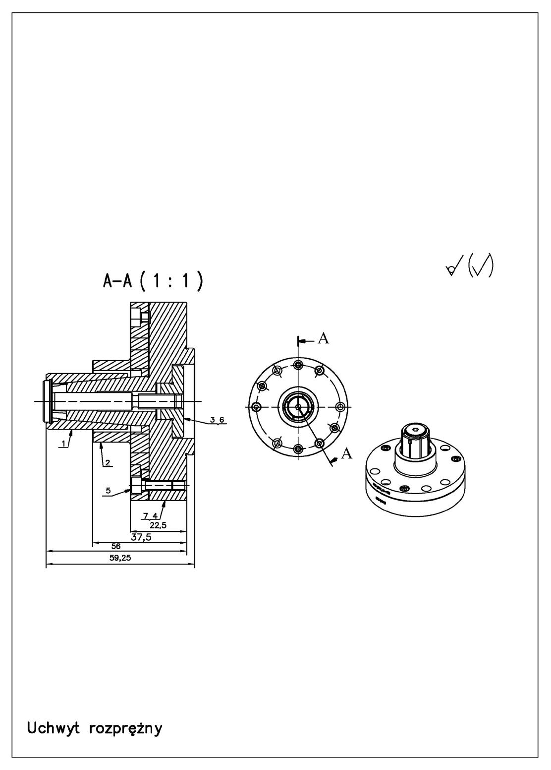
To improve the repeatability of centering, the sleeve can be optionally equipped with a pin that fixes its angular position in relation to the cone. Since there is a relative movement of the bushing along the cone, the centering repeatability of an adapter, made, for example, with the technology of an automatic machining center, is not sufficient to achieve low classes of balancing accuracy. Therefore, various post- processing procedures are used, such as mutual lapping of the bushing and cone before final cutting. The convergence of the cone is selected according to the accuracy of centering. For more accurate balancing, a reduced angle is used, but greater than the value of 1°25″ due to unfavorable self-braking.
The quality of the chuck can be measured by the value of the lateral runout of the mounted rotor. Let’s assume that systematic errors, understood as repeated in value and phase, have been eliminated. These are not errors related to the mounting of the rotor to the shaft. They can, for example, be related to the use of a drive with a gimbal shaft.
With repeated closing and opening of the adapter, we get a scattering of the measured lateral runout of the rotor. Among the measured runout values, one value can be distinguished, above which clamping happens every time. This should be understood in such a way that it is easiest to mount with a large error, and most difficult with a small error. This value of runout, which is guaranteed and gives, with such fixing, a certain additional harmful component of unbalance, was called repeatability of fixing. We want the harmful unbalance to be as small as possible and the mounting repeatability to be the best. Unbalance that has arisen due to clamping eccentricity can be eliminated, but only up to the level of clamping repeatability.
A centering error will result in static (force) unbalance. It can be minimized with compensation. A non-perpendicular support error will result in dynamic (moment) unbalance. It cannot be compensated on the machine. It is measured by the machine and compared with the permissible value for the rotor. If the adapter is not clamped by the operator, the sleeve is closed and clamped by a spring. Opening is done by an actuator, after confirming that the spindle has stopped. Automatic opening adapters are dedicated to a specific machine. This is due to the need to adjust the beginning and end of the closing process of the adapter, depending on the position of the expansion pin of the actuator. The clamping plunger opens the handle and has three specific positions in which the signals taken from the position sensors change. The machine’s operating system must distinguish between situations where the adapter:
a) is correctly closed with the rotor,
b) is closed without the rotor,
c) is open.
Engagement of rotation occurs only in the case of an adapter being correctly closed with the rotor, when the position sensors send a signal to the machine operating system, confirming the occurrence of this situation.
Implementation of the next adapter, which is equipped with the machine, must be carried out in accordance with the design assumptions, which are written in the documentation of the machine, including the DTR.
After each replacement of the adapter, the operator of the balancer must perform additional operations that mechanically adjust the adapter to the machine and increase the adequacy of the machine’s indications. It is necessary to perform:
a) a test on the compensation process,
b) check the operation of the clamping pin.
The following tasks demonstrate the centering problem:
Task 1: closing accuracy with an expansion sleeve
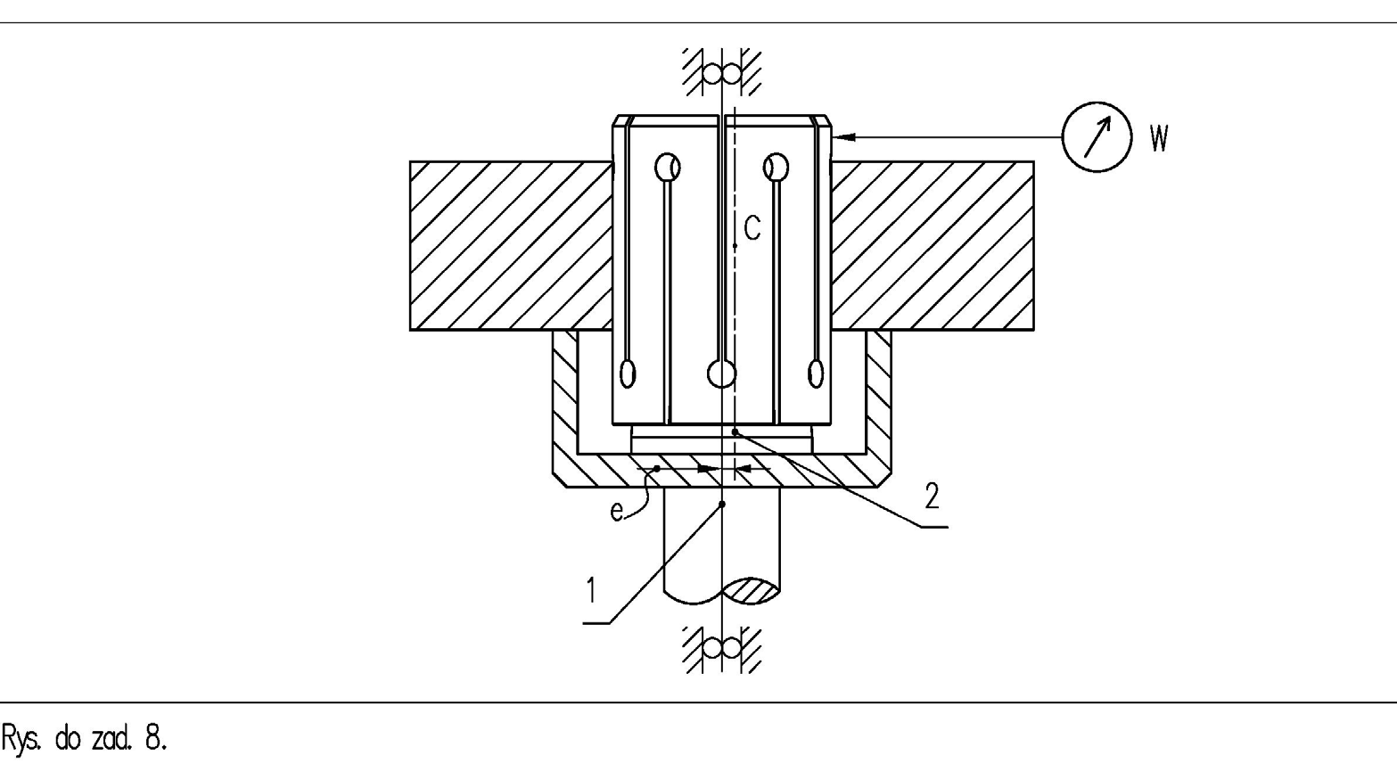
Task 1 What centering accuracy is required when closing the holder with the expansion sleeve, on the spindle of the balancing machine, to ensure the balancing of the rotor in the balancing accuracy class G2.5, assuming the hole Ø35 is made in the manufacturing accuracy class H7?
Data:
n = 2700 rpm, G2.5, M = 5 kg, w = ?.
The accuracy class of the H7 rotor hole has no effect on the residual unbalance
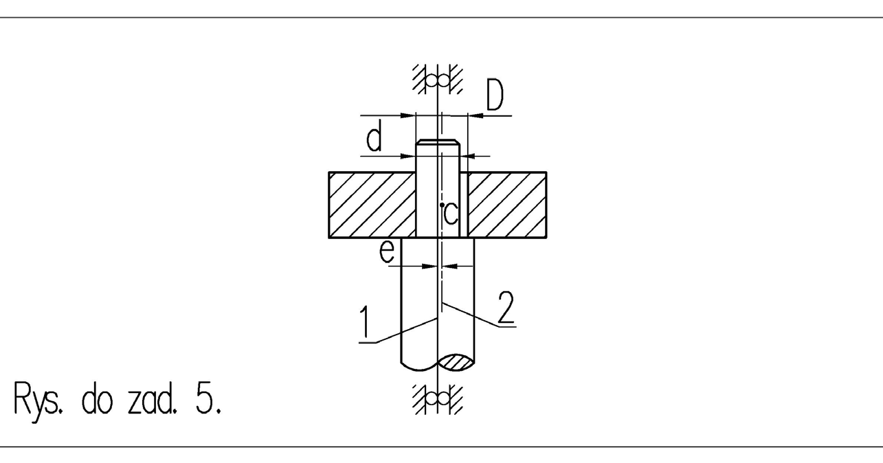
𝑒𝑒= 𝑤𝑤 2.
Calculation of allowable rotor unbalance for balancing accuracy class G2.5:
𝜋𝜋𝜋𝜋 = 30 ∙5 ∙10! ∙2.5 𝑁𝑁T = 30𝑚𝑚𝑚𝑚 3.14 ∙2700 = 44.23 𝑔𝑔𝑔𝑔𝑔𝑔.
Calculation of the allowable eccentricity of the rotor mounting:
𝑒𝑒= 𝑁𝑁T 𝑀𝑀= 44.23 5 ∙10! = 8.84 ∙10″!𝑚𝑚𝑚𝑚= 8.86 𝜇𝜇𝜇𝜇. 𝑁𝑁T = 𝑀𝑀∙𝑒𝑒 Answer: indications of the dial sensor on the side surface of the closed expansion sleeve can not be greater than 17.72μm.
Comment: the repeatability of the clamping of the chuck can be evaluated after repeated clamping and opening of the sleeve or read from the documentation of the adapter.
Adapters with a fixed mandrel
Another solution is an adapter equipped with a non-expandable, or fixed, mandrel. It is used for two basic reasons:
1. economic, when the batch count is not large,
2. when the small diameter of the hole prevents the use of an expansion sleeve.
This type of adapter is easier to make. However, the ease of making the holder results in the difficulty of obtaining a small residual unbalance. This is shown in the following tasks.
In this solution, the repeatability of the measurement results is limited by the accuracy of the rotor’s center hole. The mandrel is usually made in the upper, limiting dimension. Thus, the actual dimension of the hole determines the measurement result. The maximum possible radial runout is half of the difference between the upper deviation of the hole execution and the actual dimension of the mandrel. The unbalance shown by the machine will be the sum of the initial unbalance of the rotor and an arbitrarily, vectorially added unbalance from mounting eccentricity. With a sufficiently narrowed field of hole tolerances, the results of balancing in large series are satisfactory in practice, starting from the class towards lower accuracies (e.g.).
Adapters are made specifically for a particular type of rotor. Therefore, its shape does not have to resemble previous executions. In supercritical machines, the mass of the adapter is the so-called harmful mass. Along with part of the spindle mass, it adds to the rotor mass. As a result, the sensitivity of supercritical machines decreases, because the excitation in the form of unbalance does not change, while the excitable mass increases. In addition, the amplitude-phase characteristics change due to the different ratio of mass to excitation frequency.
Task 2: limitations of a non-expanding mandrel
Task 2 Determine what limitation, in terms of balancing, will be imposed by the use of a non-expanding mandrel in the balancing machine chuck. The mandrel has dimension d and its measured transverse runout is w. The hole in the rotor of mass M is made in the H7 manufacturing accuracy class. The rotor in the machine rotates at a rotational speed n.
Data:
d = 34.984 mm, n = 2700 rpm M = 5 kg w = 14 μm.
From the table of fits we read the values of deviations of the hole in the rotor:
𝐷𝐷= 35𝐻𝐻7 = 35!
The task will be solved in two ways:
1. with the use of compensation,
2. without the use of compensation.
Situation before compensation
Situation before compensation The spindle rotates with respect to the actual axis of rotation 1. The geometric axis of the mandrel is axis 3. The main, “!.!$%𝑚𝑚𝑚𝑚.
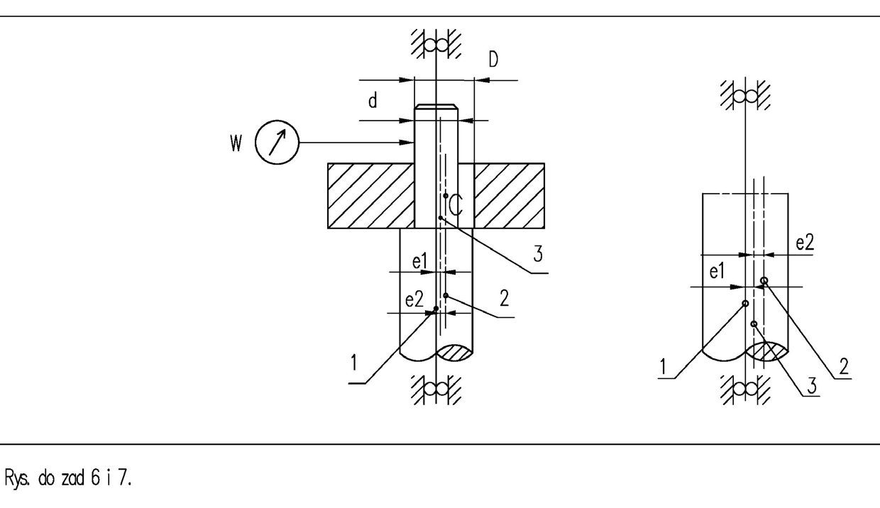
central axis of inertia of the balanced rotor, along with the center of gravity c, is axis 2.
We note that there is a clearance between the diameters of the mandrel and the rotor. Within the clearance, the rotor can be freely fixed.
Before compensation: errors in the off-center attachment of the mandrel and the rest of the adapter and spindle will affect the result in the form of accrued additional harmful unbalance. Also, an off-center mounting of the rotor, relative to the actual axis of rotation, will generate additional inertial forces throughout its mass. These, too, will be converted into harmful unbalance.
The rotor can be attached to the adapter arbitrarily (but within its clearance), with the clearance cancelled at any random angle in the plane perpendicular to the spinning axis. We assume the worst case: the runout of the mandrel and the maximum deviation of the hole execution add up in the same direction, that is, algebraically.
Eccentricity of the center of gravity position resulting from transverse runout of the mandrel:
Eccentricity resulting from making the mandrel below the nominal value and the hole in the upper deviation:
𝑒𝑒$ = ∅%&’ −𝑑𝑑 2 = 35.025 −34.984 Total eccentricity:
𝑒𝑒= 𝑒𝑒# + 𝑒𝑒$ = 0.007 + 0.0205 = 0.0275 𝑚𝑚𝑚𝑚.
Unbalance resulting from off-center rotor mounting:
𝑁𝑁T = 𝑀𝑀𝑀𝑀= 5 ∙10! ∙0.0275 = 137.5 𝑔𝑔𝑔𝑔𝑔𝑔.
Calculation of the balancing accuracy class achievable in each fixture:
𝐺𝐺= 𝑁𝑁T𝜋𝜋𝜋𝜋 30𝑀𝑀= 137.5 ∙3.14 ∙2700 30 ∙5 ∙10! Z𝑔𝑔∙𝑚𝑚𝑚𝑚∙ The total rotor unbalance, obtained, for example, on a vertical balancing machine, is the sum of the residual unbalance indicated by the machine and one of the values contained in the uncertainty area: 0<G<7.7.
Situation after compensation Determine what limitation, in terms of balancing, the use of a non-expanding mandrel in the balancer holder will impose. The mandrel has dimension d 𝑒𝑒# = 0.014 2 = 0.007 𝑚𝑚𝑚𝑚.
2 = 0.0205 𝑚𝑚𝑚𝑚. 𝑒𝑒𝑒𝑚𝑚𝑒𝑚𝑚 𝑠𝑠∙𝑔𝑔 = 7.7 ]𝑚𝑚𝑚𝑚 and the hole in the rotor of mass M is made in the manufacturing accuracy class H7. The rotor in the machine rotates at a rotational speed n.
Data:
𝑑𝑑= 35″
(0 𝑚𝑚𝑚𝑚 𝑛𝑜𝑜𝑜𝑚𝑚𝑚𝑚𝑀𝑘𝑘𝑑𝑚𝑚 𝑛𝑛= 2700 𝑜𝑜𝑜𝑜𝑜𝑜./𝑚𝑚𝑚𝑚𝑚𝑚 𝑀𝑘𝑘𝑑𝑚𝑚𝑛𝑜𝑜𝑜𝑚𝑚𝑚𝑚 𝑀𝑀= 5 𝑘𝑘𝑘𝑘.
From the table of fits we obtain the values of deviations of the hole in the rotor:
𝑠𝑠^.
D = 35𝐻𝐻7 = 35)
Situation after compensation
Compensation will eliminate those components of unbalance that have arisen from repetitive errors. These are:
a) unbalance of all spindle and adapter components,
b) unbalance of the disc, which results from its off-center mounting in the adapter.
().)$+𝑚𝑚𝑚𝑚.
The components of unbalance that arise from unique errors in disc mounting are not eliminated. The rotor can be attached to the spindle arbitrarily, but within its clearance. We assume the worst case: the clearance will clear completely in any direction.
The center of gravity of the disc lies on its main central axis of inertia 2. The actual axis of rotation of the spindle lies on axis 1.
The eccentricity of the center of gravity position is half the clearance of the disc seated on the spindle:
Unbalance resulting from off-center rotor mounting:
Calculation of the balancing accuracy class achievable in each fixture:
𝐺𝐺= 𝑁𝑁T𝜋𝜋𝜋𝜋 The total rotor unbalance, obtained, for example, on a vertical balancing machine, is the sum of the residual unbalance indicated by the machine and one of the values contained in the uncertainty area: 0<G<3.5.
𝑒𝑒= 0.025 2 = 0.0125 𝑚𝑚𝑚𝑚.
𝑁𝑁T = 𝑀𝑀𝑀𝑀= 5 ∙10! ∙0.0125 = 62 𝑔𝑔𝑔𝑔𝑔𝑔.
30𝑀𝑀= 62 ∙3.14 ∙2700 30 ∙5 ∙10! Z𝑔𝑔∙𝑚𝑚𝑚𝑚∙1 𝑠𝑠∙𝑔𝑔 = 3.5 𝑚𝑚𝑚𝑚 The use of compensation has reduced the area of uncertainty about the adequacy of unbalance indications. As a result, the value of the residual mass in the residual unbalance can be larger and easier to obtain.
𝑠𝑠.