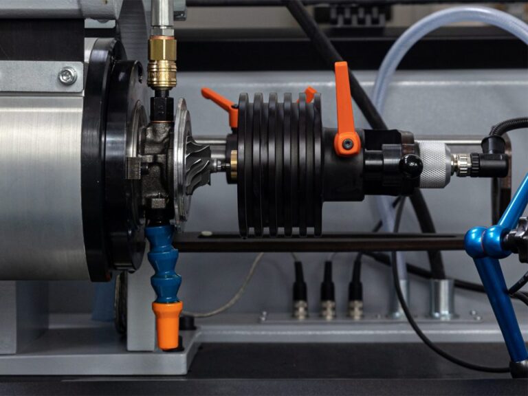
The concept of unbalance applies to both rigid and flexible rotors. On a rigid rotor, the initial unbalance is constant over the entire range of speed variation. On a flexible rotor, it is variable and depends on the rotational speed.
On a rigid rotor, the components of unbalance are:
a) uncompensated and redundant single or continuously extended, along the length, elements of the rotor material that have mass and are seated at a certain radius relative to the rotation (or vice versa: uncompensated cavities in the rotor material lying away from the axis of rotation);
b) pairs of uncompensated elements of the rotor material seated at a specified radius, relative to the axis of rotation, giving a torque in the plane containing the axis of rotation.
In the initial unbalance, in addition to the components present on rigid rotors, there may also be an initial deflection, the radius of which is constant throughout the rotation range.
On a flexible rotor, the components of unbalance are:
a) both components previously listed,
b) resulting from deflection, depending on the instantaneous speed of rotation, and thus the distance of individual unit lengths of the rotor from the axis of rotation.
Unbalance as a state and as a physical quantity
Unbalance can be considered as a state or as a physical quantity derived from SI units Unbalanced condition is understood as a type of loading by forces and moments of a mechanical system in rotary motion. The load is directly caused by such a distribution of the rotor mass, around the actual axis of rotation, which induces varying forces on the supports (which are ties for the rotor) and causes additional bending of the rotors. The load condition has defined characteristics and affects the behavior of this system. A feature of unbalance is the presence of only forces, only moments or a mixture of both physical quantities. Likewise, it causes the rotor to acquire certain dynamic parameters, such as those associated with the first eigenmode of motion of a rigid rotor or the deflection of a flexible rotor.
Analyzing the state of unbalance from the point of view of kinetostatics, we find that it can be determined in two ways:
a) by means of principal vectors fixed at the rotor’s center of gravity or other selected point through determining the principal force vector and the principal moment vector from the unbalance;
b) or by means of two force vectors, different in value and direction, lying in two planes far apart along the axis of rotation.
The principal force vector is an invariant of the unbalance condition, while the value and direction of the principal moment depend on the choice of reference point. The values and directions of two forces seated in two measuring planes depend on the position of these planes.
A review of unbalance terminology
A review of unbalance terminology Unbalance as a physical quantity is the product of mass and distance from the axis of rotation. Below is a look at various unbalance terms and subsequent definitions.
• Unbalance vector: a vector whose length corresponds to the value of unbalance, and whose direction of action is consistent with the angular location of the unbalanced mass.
𝑁𝑁”#⃗= 𝑚𝑚∙𝑟𝑟⃗ [𝑔𝑔∙𝑚𝑚𝑚𝑚, 𝜑𝜑] • Unbalance value: unbalance quantified, without consideration of the angle of action, as the product of the unbalanced mass and the distance of its center of mass from the actual axis of rotation.
𝑁𝑁” = 𝑚𝑚∙𝑟𝑟 [𝑔𝑔𝑔𝑔𝑔𝑔] 𝑚𝑚! [𝑔𝑔] • Unbalance mass: the mass, designated , which is mentally fixed at a certain radius (conventional mass) on the rotor, such that its value multiplied by the square of the rotational frequency and radius will give the value of the force from the unbalance.
• Principal vector of unbalance: formed by geometrically summing all unit forces from unbalance occurring along the entire length of the rotor. The vector is equal to the product of the mass of the rotor and the eccentricity of its center of gravity. It is perpendicular to the rotor axis and passes through its center of gravity or another selected point on the axis of rotation.
• Unbalance moment: the vector product of unbalance and the arm of its action . The vector is perpendicular to the plane determined by the rotor axis and the unbalance vector. The modulus of the unbalance vector is equal to the product of the unbalance value and the distance of the unbalance vector from the plane perpendicular to the axis against which the moment is calculated.
[𝑔𝑔𝑚𝑚𝑚𝑚”] • Unbalance principal moment: the geometric sum of all unbalance moments calculated with respect to the center of gravity of the rotor or other selected point. The vector is at the same time perpendicular to the main, central axis of inertia of the rotor.
• Static unbalance: a state of unbalance in which the actual axis of rotation and the main, central axis of inertia of the rotor are parallel. The rotor’s center of mass (center of gravity) is eccentrically located with respect to the actual axis of rotation. With static unbalance, the moment principal vector is zero and the force principal vector has a finite value.
• Moment unbalance: an unbalanced condition in which the real axis of rotation and the main, central axis of inertia intersect at some angle at the center of mass of the rotor. With such unbalance, the principal force vector is zero and the principal moment has a finite value. The center of mass lies on the actual axis of rotation.
• Quasi-static unbalance: a condition of unbalance at which its principal, central axis of inertia intersects with the actual axis of rotation beyond the center of mass. In addition, the condition of perpendicularity of the main moment vector to the plane determined by the two aforementioned axes is still satisfied.
• Dynamic unbalance of a rigid rotor: customarily referred to as an unbalance condition, containing both force and moment components. With it, the actual axis of rotation and the main, central axis of inertia are oblique to each other. If the unbalance is represented by a principal vector and a principal moment, hooked at the center of gravity of the rotor, the two vectors are inclined to each other at a specific angle. If the unbalance is represented in the form of two force vectors placed in two correction planes, spaced apart along the length of the rotor, these vectors have different lengths and act at different angles.
• Initial unbalance of a rigid rotor: state of unbalance existing on the rotor before balancing. May include both force and moment components of unbalance.
• Acceptable residual unbalance: state of unbalance existing on a rotor after a balancing process that meets the rotor’s design conditions.
Components of unbalance as forcing on the rotor
The components of unbalance create forces that are forcing for the rotor A rigid rotor does not show where, along its length, and at what angle, forces are generated. It can be concluded that the observed behavior of the rotor, during rotation, is due to the action of the sum of all the component forces from unbalance. This is because the rotor is rigid and responds to the entire load by linear motion of the center of gravity and rotation around this center. For balancing, a corresponding model of the unbalanced rotor should be created. The model should be compatible with the balancing method.
If during the balancing process we want to eliminate or minimize the above components of unbalance, then two correction planes must be adopted. They should be seated as far apart as possible along the length of the rotor. Two planes make it possible to change not only the force but also to change the moment of force.
Speed dependence of rigid rotor unbalance
The unbalance of a rigid rotor does not change when the speed is changed. After changing the support locations, it can change if the rotor exhibits constant deflection or the rotor shaft has radial runout between its sections. This can occur if, for example, it has not been machined at one mounting.
When balancing rigid rotors, the fact that we do not know the distribution of unbalance along the axis of rotation is irrelevant. The balancer, measuring the unbalance of a rigid rotor, calculates two “resultants” whose values and directions depend both on all unidentified forces acting in different planes perpendicular to the rotor axis and on the position of correction planes taken for measurement and correction, along this axis. The calculated unbalance values do not change in value or direction with changes in speed, although the balancer indications usually vary. The constancy of the calculation results is guaranteed by taking calibration coefficients suitable for the selected rotational speed and for the selected positions of the correction planes.
The calculated unbalance values do not change in value and direction with changes in rotational speed, although the indications of the balancer usually vary. The constancy of the calculation results is guaranteed by taking calibration coefficients suitable for the selected rotational speed and for the selected positions of the correction planes. In determining these coefficients, the dynamic properties of the rotor, that is, the amount of its mass and its ideally compensated distribution along its length, are important. It can only be added that the forcing for different speeds varies, since the sum of component motions performed according to the first and second forms of vibration in supercritical balancers is different. There, the support vibration systems consist of an unknown amount of mass spanning the rotor, support elements, and even parts of the machine bed. These can be called substitute masses.
We don’t identify these masses and can’t easily do so.
On subcritical balancing machines the indications also change, regardless of the constancy of unbalance, when the measuring speed and the positions of the measuring planes are changed. The change in the position of the correction planes is taken into account automatically by the machine, by entering data on the new positions of these planes along the length of the rotor from the keyboard of the measuring module. The calibration coefficients are built differently here. They do not, in fact, depend on the dynamic properties of the rotor. They depend only directly proportional to the rotational speed (that is, they are easy to count). For the calculation of unbalance, the geometric dependencies of the rotor and its support location are used in accordance with the principles of kinetostatics.
Balancing a flexible rotor
A flexible rotor, balanced at a certain speed, is not balanced at any other speed. The question arises: can a flexible rotor be balanced to zero? The answer to the question posed is that it is not possible to balance to zero, but it is possible to practically minimize the effect of unbalance on deflections so that at the rotational speeds used there will be no deflections greater than those accepted as acceptable. In practice, it is decisive to minimize the first two (in special cases, three) forms of deflections. As the rotational speed increases, the effect on deflection of the components of unbalance (including static, momentary and mixed unbalance) is revealed. Each of these components forces resonance at a specific rotational speed.
Distribution into two correction planes
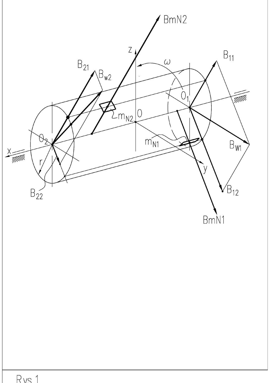
Figure 1 shows redundant weights with masses and occurring at arbitrary locations on the rotor. They cause the rotor to be loaded with inertia forces and . There can be any number of such weights generating inertia forces from unbalances. This number, or the locations of the weights, will not be known during identification.
On a rigid rotor, any inertia force is replaced by two forces occurring in both correction planes. In the figure, for example, these are and relating to the load . Other forces are replaced in the same way.
The decomposition of the force into two components follows the principles of kinetostatics (it can be done by solving a system of two statics equations: the sum of the forces in the direction of their action and the sum of the moments relative to, for example, one of the correction planes). Assume that there are as many force components in both correction planes as there are excess masses on the rotor. In each plane, separately, the component forces are added up to the resultant ones. In the balancing process it is sufficient to add one weight (in the form of correction weights) per side of the rotor as counterweights giving opposite inertial forces to the resultant ones. If the sum of the resultant and corrective forces is close to zero, then the rotor is balanced. In practice, residual 𝑚𝑚!”
𝐵𝐵$!# 𝐵𝐵$!”
𝐵𝐵## 𝐵𝐵”# 𝑚𝑚!# unbalance remains. For balancing to be considered effective, the residual unbalance must be less than acceptable.
This is the primary way to show the forceful effect of unbalance on the rotor.
Principal vector and principal moment
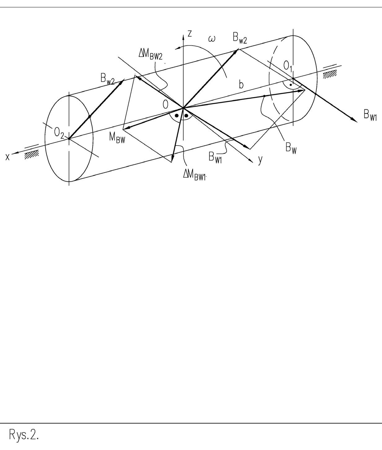
Figure 2 shows the same unbalance but in the form of the so-called principal vector and principal moment of unbalance. In this case, the outputs are vectors of resultant forces determined in both correction planes and .
𝐵𝐵%# 𝐵𝐵%”
After moving the two vectors in parallel to a common point, such as the center of gravity, the resultant is obtained from them. Its direction and the length of the resultant do not depend on the position of the point along the length of the rotor. Thus, the resultant force from unbalance is a load invariant.
𝐵𝐵% Shifting should be done so that the load on the rotor, before and after shifting, is the same. To offset the effect of the shifted force on the rotor, the rotor must be loaded with an additional moment of force. As the force tries to rotate the rotor around the axis, passing through point 0, the moment must try to rotate the rotor in the same way. The value is derived from the vector product . . The direction of the moment vector is perpendicular to the plane on which the two vectors lie and has a turn according to the right-hand screw rule.
𝐵𝐵%# 𝑀𝑀##⃗(𝐵𝐵%#) = 𝐵𝐵#⃗%# × 𝑏𝑏#⃗ Here, the principal moment has two components derived from the displacement of two forces. When you select another point lying on the geometric axis, the moment components will change. The principal moment of unbalance is not an invariant of the load.
Unbalance as the static moment of the correction load
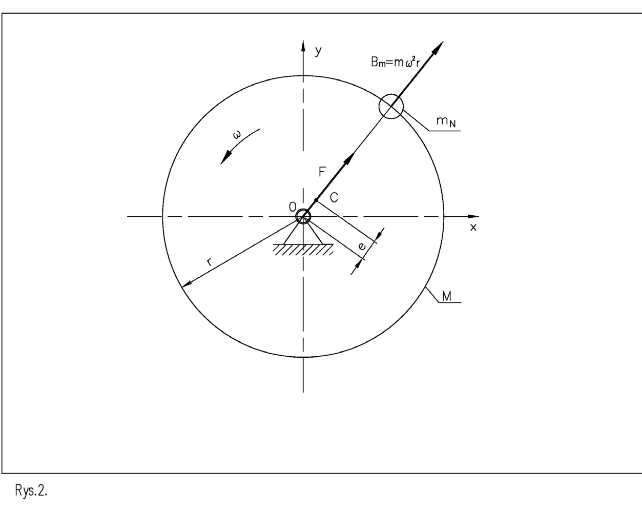
Unbalance as a physical quantity is the static moment of the correction load. In other words, it’s the product of the excess mass and the distance of the center of that mass from the actual axis of rotation. Both before and after balancing, we do not know the locations of circularity deficiencies. It is assumed that any lack of circularity is in the form of an excess mass , which is seated on the edge of the disc or on the diameter of the rotor shaft.
𝑚𝑚!
𝑚𝑚!
𝑁𝑁” = 𝑚𝑚! ∙𝑟𝑟 [𝑔𝑔𝑔𝑔𝑔𝑔] The static unbalance of the disc is:
.
The displacement of the center of 𝑒𝑒= ()$! ≅ $!∙’ $!∙’ gravity is:
( [m] This is calculated from the equilibrium of the static moments of the excess mass founded on the radius of the rotor (r) and the total mass on the eccentricity (e).
Axes of inertia and the ellipsoid of inertia
To analyze and calculate the motion of a rotor having mass, the concept of axes of inertia, mass moments of inertia and the ellipsoid of inertia was introduced. The ellipsoid of inertia is constructed using three axes that are perpendicular to each other. So-called mass moments of inertia, which describe the mass distribution of the rotor, are calculated on each direction. Of all the positions acting in any direction, we distinguish axes of inertia acting in specific directions. These are the main and central at the same time, and only the main axes.
The principal ones have such a direction, with respect to the rotor, that the mass moments of inertia take on extreme values. If, in addition, they pass through the center of gravity, they are called principal and central. The sum of the principal and central values is always the smallest (due to the addition of moments resulting from Steiner’s theorem). Taking the extreme values of the moments of inertia means that one moment has the largest value (which is always calculated according to the adopted procedure), another has the smallest possible to calculate, and the third has an intermediate value. When the rotor’s actual axis of rotation and one of the main and central axes of inertia coincide, the rotor is not loaded with any uncompensated inertia forces.
There is no unbalance on it. We note that on the main directions (centrally located with respect to the mass of the rotor), all mass fines located on one side of the axis of rotation has its counterpart exactly on the opposite side of rotation.
If the axes of rotation and the main, central axis are not parallel, but intersect at the point of the center of mass, moment unbalance is created. If they intersect at another point or are oblique with respect to each other, force as well as moment unbalance arises. When they are parallel, only force unbalance arises.
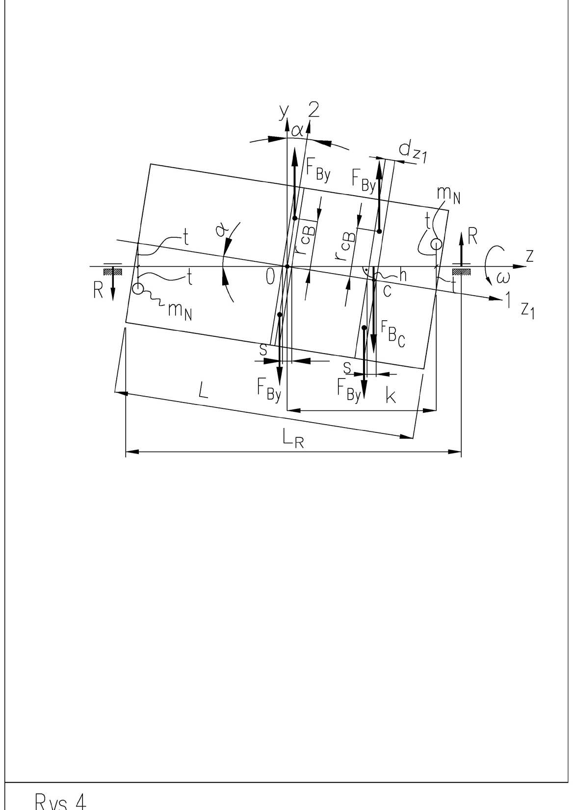
The main and central axes of inertia in Figure 4 are named: 1 and 2. They intersect at the center of gravity c, so there is a moment from uncompensated inertia forces.
Two cases of angular mounting error
We will consider two cases:
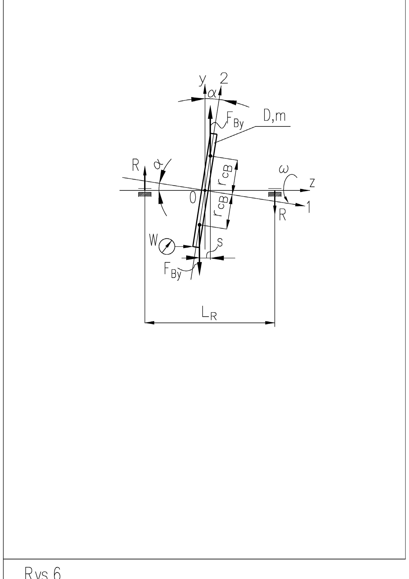
a) rotating thin disc attached to an axis with angular error, the thickness of which is to be ignored
b) spinning rotor, having length L, fixed in bearings so that its principal and central axis of inertia intersects the axis of rotation at the point of its center of mass If we assume that the disc has mass m and diameter D and is attached to a massless shaft with axial runout W, its load is a pair of inertia forces.
# where:
$ And has a straightening effect on the shield.
This is the resultant force from one half of the disc. It replaces all inertia forces present on one half of the disc. Since the amplitudes of the forces are directly proportional to the distance from the axis of rotation, the location of the resultant from one half of the disc does not lie in the center of mass of the disc half.
Recall, by the way, that the center of gravity of one half of the disc lies at a distance of 0.2122D from the diameter dividing the disc into two halves.
F0% r1& = 0,2945D𝑀𝑚𝜔𝐷 The force is hooked at a distance:
.
The straightening moment of the disc is: .
The moment will induce reaction forces in the supports of the shaft:
Hence the force in the support is:
The rotor of length L is fixed in bearings so that its main and central axis of inertia 1 intersects at the center of mass c at an angle α with the spin axis. The mounting error can also be measured as the radial runout W on both sides of the rotor. In this case, the run-outs have equal values (and the maxima are, relative to each other, angularly displaced by 180°).
= /, 𝛼𝛼= 𝑎𝑎𝑎𝑎𝑎𝑎sin H /I .
.
𝑅𝑅= # The rotor is loaded with moment from uncompensated inertia forces.
You can count these forces, for example, by imagining that it consists of multiple discs, as in Figure 4. The load on the center disc is described in Figure 5. Each different one is additionally loaded by a moment from the force resulting from the eccentric position of its center of gravity, , with respect to the spin axis. Taking both components into account, the value of the moment can be calculated from the equation formed by summing the above- described load components:
𝑀𝑀+ = 𝑚𝑚𝜔𝜔” sin 𝛼𝛼cos 𝛼𝛼H Where: m-mass [kg], D diameter of the rotor [m], L-length [m] ω-frequency resulting from rotor rotation .
In the above equation, we note that for a certain value of D and L, regardless of the value of radial runout at the ends of the shaft, the torque of the entire rotor is zero.
Let’s check this condition, at which no torque will occur:
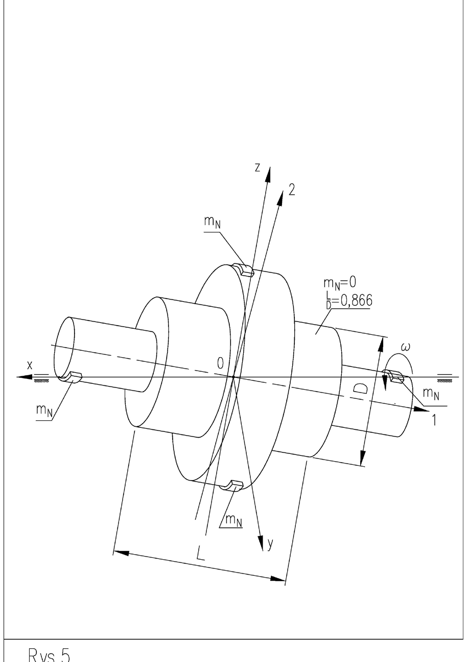
𝐿𝐿= √3 We also note that for a rotor length- to-diameter ratio the sign of the torque induced unbalance changes.
𝐹𝐹*)
#3 𝐷𝐷” − #” 𝐿𝐿”I (4), # # 6X W# #3 𝐷𝐷” = #” 𝐿𝐿”, # # 2 𝐷𝐷= 0,866𝐷𝐷.
/ = √8 ” , This means that for we attach / > √8 correction weights on the “light” side and for on the “heavy” side at the ends of the rotor. This is shown in Figure 6.
𝑀𝑀+]𝑚𝑚!,#)”^ = 2𝑀𝑀+]𝑚𝑚!,#^ = 1 Comparing the total torque from equation (4) with the above allows their masses to be determined without depending on the value of the angle :
𝑚𝑚! = 5$ 𝑚𝑚H # / > √8 “
“
𝑚𝑚!
2 𝑚𝑚!𝜔𝜔”𝐿𝐿” sin 𝛼𝛼cos 𝛼𝛼 𝛼[𝑁𝑁𝑁𝑁].
φ#3 𝐷𝐷” − #” 𝐿𝐿”I𝑚𝐿 [𝑘𝑘𝑘𝑘].
“
# Thus, the expression shown is an invariant of the rotor, which has a certain slenderness, that is, the ratio of diameter to length. The value of the mass , calculated in this way, and seated at a distance (t) from the actual axis of rotation, does not depend on the angular error α of the foundation of the rotor when the load is fixed at a distance (t) from the actual axis of rotation (Figure 5). It indicates the phase of foundation of the load on the “light” or “heavy” side of the rotor.
𝑚𝑚!
Correction weights and support forces
Of practical importance are comparisons of the moment from the inertia force, caused by the foundation of the correction weight at the ends of the rotor, on its diameter, with the moment determined in equation (4):
𝑚𝑚!𝜔𝜔” 𝐷𝐷 2 𝐿𝐿= 𝑚𝑚𝜔𝜔” sin 𝛼𝛼cos 𝛼𝛼_ 1 16 𝐷𝐷” −1 12 𝐿𝐿”` (5), where the left side of the equation is the inertia force from calculated from the definition of .
Hence, the mass of a single correction weight is:
𝑚𝑚! = 2𝑚𝑚 𝐷𝐷𝐷𝐷sin 𝛼𝛼cos 𝛼𝛼_ 1 If the distance between the weights are L and the weights are seated on the radius D/2, the moment unbalance will be by definition:
𝑁𝑁”(9$ = 𝑚𝑚!
𝑚𝑚!
𝑚𝑚!
16 𝐷𝐷” −1 12 𝐿𝐿”` [𝑘𝑘𝑘𝑘].
𝐷𝐷 2 𝐿𝐿 [𝑘𝑘𝑘𝑘∙𝑚𝑚”].
As the angle α takes small values, the following can be assumed with sufficient accuracy:
sin 𝛼𝛼= 𝛼𝛼 [𝑟𝑟𝑟𝑟𝑟𝑟], cos 𝛼𝛼= 1 The relationship simplifies to:
𝑚𝑚! = 2𝑚𝑚 𝐷𝐷𝐷𝐷𝛼𝛼_ 1 16 𝐷𝐷” −1 12 𝐿𝐿”` [𝑘𝑘𝑘𝑘], 𝛼𝛼→ [𝑟𝑟𝑟𝑟𝑟𝑟], 𝐷𝐷, 𝐿𝐿→[𝑚𝑚], 𝑚𝑚→[𝑘𝑘𝑘𝑘].
where:
It is also practical to determine the value of the force that occurs in both supports of the rotor, where we use the balance of the moments of force derived from the support reactions and determined in equation (4):
𝑅𝑅𝐿𝐿4 = 𝑚𝑚𝜔𝜔” sin 𝛼𝛼cos 𝛼𝛼_ 1 16 𝐷𝐷” −1 12 𝐿𝐿”`.
Hence, the force in the support is:
𝑅𝑅= 1 𝑚𝑚𝜔𝜔” sin 𝛼𝛼cos 𝛼𝛼_ 1 16 𝐷𝐷” −1 12 𝐿𝐿”` c𝑘𝑘𝑘𝑘∙𝑚𝑚 𝑠𝑠” e →[𝑁𝑁] 𝐿𝐿4 or after simplification:
𝑅𝑅= 1 𝑚𝑚𝜔𝜔”𝛼𝛼_ 1 16 𝐷𝐷” −1 12 𝐿𝐿”`, 𝐿𝐿4 𝛼𝛼→[𝑟𝑟𝑟𝑟𝑟𝑟], , 𝐷𝐷, 𝐿𝐿4 →[𝑚𝑚], 𝑚𝑚→[𝑘𝑘𝑘𝑘].
Where:
The forces in both supports, caused by the torque generated on the rotor, have the same values regardless of the location of the rotor between the supports.
Using the determined values of the forces, it is possible to determine the amounts of the masses of the correction weights, which, being seated on the width of the supports, must rotate with the rotor on the radius / “:
𝑚𝑚:9′ = 2𝑅𝑅 𝜔𝜔”𝐷𝐷= 2 𝐿𝐿4, If the distance between the weights is the moment unbalance will be:
𝑁𝑁”;<= = 𝑚𝑚:9′
Summary
- Unbalance can be regarded as a condition of external load, which is a forcing on the rotor during rotation. This forcing has components: static, in the form of centrifugal forces, and dynamic, in the form of torque, acting in the plane containing the axis of rotation.
- The unbalance of a rigid rotor can include both of the above components of unbalance. The unbalance of a flexible rotor contains, in addition, an unbalance stretched over the entire length of the rotor, resulting from deflection, and is built from the product of the mass per unit length of the rotor and its distance from the axis of rotation. The deflection can be spatial.
- The unbalance of a rigid rotor does not depend on the rotor speed.
- 𝑚𝑚:9’𝜔𝜔” 𝐷𝐷 2 = 𝑅𝑅, 𝑚𝑚𝛼𝛼_ 1 16 𝐷𝐷” −1 12 𝐿𝐿”` f𝑘𝑘𝑘𝑘∙𝑚𝑚”
- 𝑚𝑚” g →[𝑘𝑘𝑘𝑘].
- 𝐷𝐷𝐷𝐷4 𝐷𝐷 2 𝐿𝐿4 = 𝑚𝑚𝑚𝑚_ 1 16 𝐷𝐷” −1 12 𝐿𝐿”` [𝑘𝑘𝑘𝑘∙𝑚𝑚”].
- The unbalance of a flexible rotor depends on the speed.
- The unbalance of a rigid rotor can be represented by the so-called principal vector and principal moment of unbalance, or by two unbalance vectors, or inertia forces, which are offset from each other along the length of the rotor and have different lengths and act in different directions.
- Static unbalance is usually measured in or It is the result of multiplying the excess mass centered at a point, seated at a distance r from the axis of rotation.
- 𝑚𝑚!,
- Moment unbalance is usually measured in or as it is formed by pairs of static unbalances that are spread along the length of the rotor.
- / > 0,866,
- For a length-to-diameter ratio of the moment changes the direction of action from righting to enlarging the moment unbalance. Dr. Mirosław Malec, Eng. Former President of Przedsiębiorstwo Cimat Sp. z o.o.
- [𝑔𝑔𝑔𝑔𝑔𝑔] [𝑘𝑘𝑘𝑘𝑘𝑘].
- [𝑔𝑔𝑚𝑚𝑚𝑚”]𝑘𝑘𝑘𝑘𝑟 [𝑘𝑘𝑘𝑘𝑚𝑚”],