A gyroscope rotor spinning at 150.000 rpm inside an inertial navigation system is one of the most precisely balanced manufactured objects in existence. At those rotational speeds, even a fraction of a milligram of imbalance generates forces that cause bearing wear, vibration, and most critically, drift in the navigational output that the gyroscope is supposed to provide.
For defense systems that depend on inertial navigation, such as cruise missiles, strategic weapons, submarines operating without GPS and spacecraft, the accuracy of the navigation system is bounded by the quality of the gyroscope. And the quality of the gyroscope is bounded, in part, by how precisely its rotor was balanced during manufacturing.
Why Gyroscope Balancing Is Uniquely Demanding
Gyroscope rotor balancing occupies a category of its own within the broader field of dynamic balancing. The requirements are orders of magnitude tighter than even aerospace propulsion balancing, for several reasons:
Operational speed. Small gyroscope rotors can operate at speeds up to 150.000 rpm. At those speeds, centrifugal forces amplify any mass asymmetry enormously. A 1 mg imbalance at a 10 mm radius generates a centrifugal force that scales with the square of the rotational speed — meaning the same imbalance produces 100× more force at 10.000 rpm than at 1.000 rpm.
Tolerans birimleri: mg·mm. Jiroskop balanslama toleransları, dengesizlik kütlesinin ve spin ekseni ile olan uzaklığının çarpımı olan mg·mm cinsinden belirtilir. Düzeltme yarıçapında miligram kesri bile ölçülebilir titreşim, yatak aşınması ve navigasyon sapmasına neden olur. Karşılaştırma için, endüstriyel motor balanslama toleransları tipik olarak g·mm cinsinden belirtilir ve bu da üç büyüklük sırası daha az talep edicidir.
Bearing life and drift. Gyroscope rotors run on precision bearings, such as gas bearings, jewel bearings or magnetic suspension, that are designed for minimal friction and maximum stability. Imbalance-induced vibration accelerates bearing wear, which in turn degrades the gyroscope’s rotational stability, creating a compounding error that worsens over the system’s operational life.
Navigasyon doğruluğu bağlantısı. Jiroskopun amacı dönüşü algılamak ve ölçmektir. Rotor'daki herhangi bir titreşim veya sallanma, dengesizlik kaynaklı presisyon gibi gerçek dönüş olmayan, jiroskopun çıkış sinyalini kontamine eder. Bu kontaminasyon, eylemsiz navigasyon sisteminin çıkışında sapma kararsızlığı ve açısal rastgele yürüyüş gürültüsü olarak görünür ve navigasyon doğruluğunu doğrudan düşürür.
Types of Imbalance in Gyroscope Rotors
Gyroscope rotor imbalance takes the same three forms as any rotating component (static, couple and dynamic), but the consequences at gyroscopic speeds are far more severe.
Static imbalance: The center of mass is offset from the spin axis and the rotor is “heavy on one side.” This creates a rotating force vector at the spin frequency that loads the bearings cyclically.
Çift dengesizlik: atalet ana ekseni, dönme geometrik eksenine göre açısal olarak yer değiştirmiştir. Rotor'un kütle dağılımı boyunca çarpıktır ve her bir yatak noktasında eşit ve zıt kuvvetler oluşturarak sallanma momenti meydana getirir. Çift dengesizlik jiroskoplarda özellikle sinsi bir sorundur çünkü jiroskopun ölçmek için tasarlandığı dönüşü doğrudan taklit eden spin ekseni üzerinde bir tork oluşturur.
Dynamic imbalance: The vector sum of static and couple imbalance. This is the general case for real-world rotors and requires measurement and correction at two planes.
The Balancing Process for Gyroscope Rotors
The balancing sequence for gyroscope rotors follows the same fundamental steps as any dynamic balancing process but with specialized equipment and techniques appropriate to the tolerance regime.
1. Precision Measurement
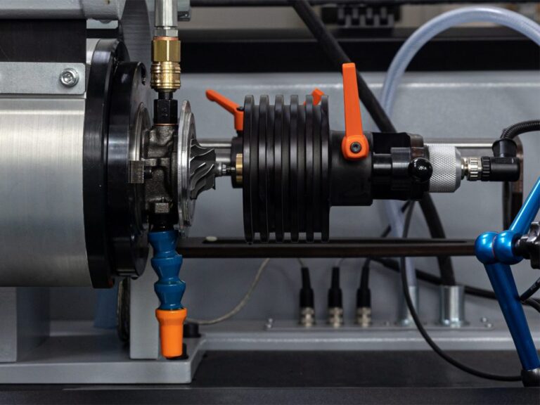
The rotor is mounted on a precision balancing machine that is fundamentally similar in principle to a wheel balancing machine, but orders of magnitude more precise. The machine’s bearing system, vibration sensors and signal processing are designed to resolve imbalances in the sub-mg·mm range.
The rotor is spun at a controlled speed (not necessarily the full operational speed, instead the measurement speed is chosen to provide adequate signal-to-noise ratio while remaining within the machine’s safe operating envelope). Vibration sensors detect the imbalance signature at each correction plane, providing both magnitude and angular position.
2. Material Correction
Correction is performed by either removing or adding material at calculated positions.
Material removal methods
- Micro-drilling: Precisely controlled drilling of small holes at the calculated angular position to remove the excess mass
- Micro-grinding: Surface material removal for corrections that require distributed removal rather than point removal
- Laser ablation: The most precise removal method, capable of removing material in microgram quantities at exact positions. Laser ablation is increasingly the preferred method for the tightest tolerances because it introduces no mechanical stress and can be controlled with extreme precision
Material addition methods
- Correction weights: Small precision weights affixed at the calculated angular position
- Epoxy resin: Precisely dispensed at the correction position, cured in place. Useful when the rotor geometry does not permit drilling or grinding at the required angular position
3. Iterative Verification
The corrected rotor is re-spun and re-measured. Because each correction changes the rotor’s mass distribution, the correction process is inherently iterative, meaning each correction may require a verification spin and potentially a second correction to converge within tolerance.
For the tightest tolerances, three or more correction iterations may be required. The balancing machine’s measurement system must be stable and repeatable enough that the residual readings after correction reflect the actual rotor state — not measurement noise.
Where Balancing Fits in the Defense Gyroscope Pipeline
Mechanical balancing is one stage in a multi-stage process that takes a gyroscope from raw material to a flight-ready navigation instrument:
| Stage | What Happens |
|---|---|
| Component manufacture | Rotor machined to tight dimensional tolerances |
| Mechanical balancing | Residual imbalance corrected on precision balancing rig |
| Assembly and burn-in | System run at temperature to stabilize bearings and materials |
| Calibration | Multi-axis rate table testing, thermal cycling, error model generated |
| In-service re-calibration | Some systems continuously self-correct using reference measurements |
Mechanical balancing is the foundational step because it establishes the physical quality of the rotor that all subsequent calibration and compensation depend on. A poorly balanced rotor will generate vibration and drift that calibration can partially compensate for in software but cannot fully eliminate at the physical level.
The Cimat Approach
Cimat, an Ascential Technologies brand, builds precision balancing machines designed specifically for the defense gyroscope manufacturing environment complete with measurement resolution in the sub-mg·mm range, automated correction guidance, iterative verification capability and full data traceability for every rotor balanced.
The combination of measurement precision, correction optimization (minimizing material removal while achieving tolerance) and production traceability is what makes defense gyroscope balancing a specialized discipline — and what makes the balancing machine a critical piece of defense manufacturing infrastructure.